Linearity compensation by harmonic cancellation

US6911925B1Active Publication Date: 2005-06-28TEKTRONIX INC

Image

  • Linearity compensation by harmonic cancellation
  • Linearity compensation by harmonic cancellation
  • Linearity compensation by harmonic cancellation

Examples


Embodiment Construction

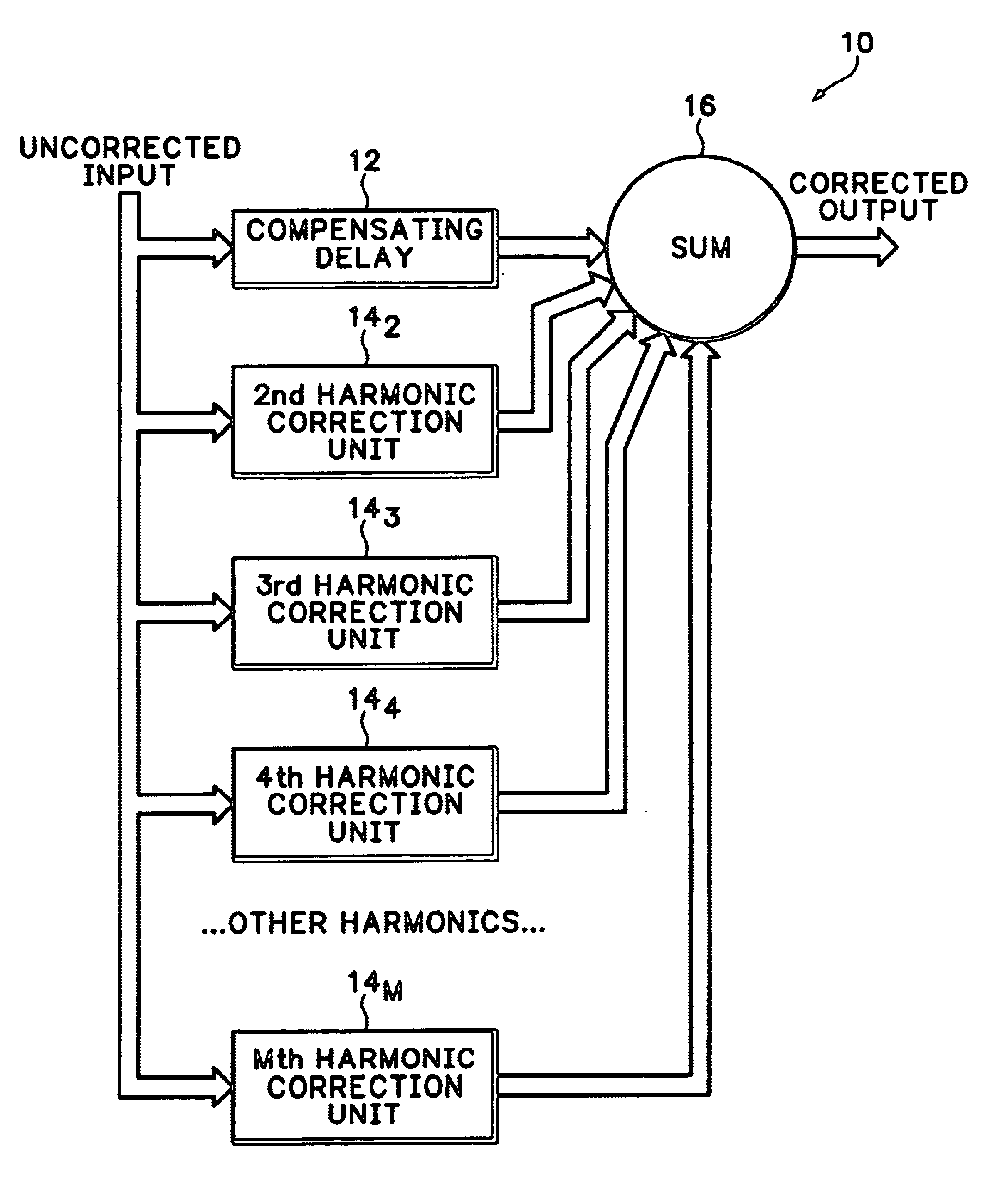
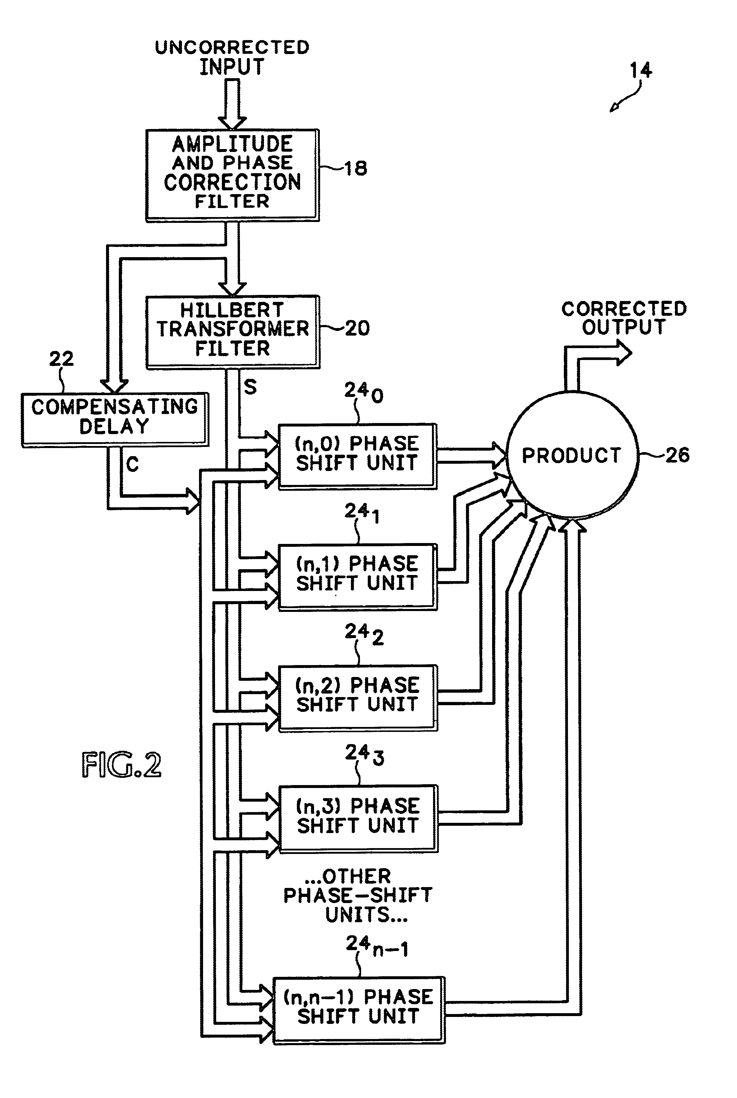
[0028]Self-modulating harmonic distortion mechanisms are based on the formation of a product of delayed versions of an input signal within a nonlinear system, such as a multi-stage ADC. It is difficult to infer the delays on each path of the input signal to this system. In the special case where they have the same phase, the above-described harmonic profile of the prior art is appropriate. In actual systems any combination of phases is possible. In another particular case a set of evenly spaced phase relationships produce only the desired harmonic. This has the advantage that each harmonic may be independently calibrated for cancellation. The disadvantage is that some additional processing is involved. The present invention uses the following product over evenly spaced phase shifts on the assumption that delays map to phase shifts if the sample clock rate is not changed between calibration and operation:

sin(n,ωt)=2n−1Πk=0→n−1sin(ωt+kπ / n)

Using a trigonometric expansion, this becomes...


PUM


Abstract

A linearity compensation circuit provides cancellation of harmonic distortion introduced by a non-linear system into an input signal by providing a separate harmonic correction component for each harmonic of a fundamental frequency of the input signal. The harmonic correction components are summed with a delayed version of the input signal to produce a corrected input signal for input to the non-linear system. The separate harmonic correction components are generated by respective harmonic correction units, each having a programmable input filter, a Hilbert Transformer filter and a plurality of phase shifters. The output of each programmable input filter is input to the Hilbert Transformer filter and a compensating delay. The output from the Hilbert Transformer filter and the delayed version of the filtered input signal from the compensating delay are input to parallel phase shifters, and the respective outputs from the phase shifters are multiplied together to produce the separate harmonic correction component for each harmonic correction unit.

Description

BACKGROUND OF THE INVENTION[0001]The present invention relates to linearity error correction, and more particularly to a method of linearity compensation by canceling harmonics generated in signal processing systems, such as analog-to-digital converters (ADCs).[0002]Distortion is generated by all types of non-linear systems, i.e., systems S( ) whereS(f(t)+g(t))≠S(f(t))+S(g(t)) where f(t) and g(t) are two signals. If an input to a non-linear system is repetitive over a certain period T, then its passage through a memory-less non-linear system is also repetitive over the same period. Fourier theory requires that:[0003]a) all repetitive signals of period T may be expressed as a sum of a DC offset, a fundamental sine wave of period T, and the harmonics of the fundamental;[0004]b) the fundamental and harmonics each have an amplitude and phase that is uniquely defined by the shape of the repetitive signal.[0005]A sine frequency is the reciprocal of its period or cycle time, so the fundame...

Claims


Application Information

Patent Timeline
28 Jun 2005
Publication
US6911925B1
IPC
H03M1/06; H03M1/08; H03M1/14; H03M1/12; H03M1/38; H03M1/44; H03M1/16; H03F1/32
CPC
H03M1/0614; H03M1/0626; H03M1/44; H03M1/164; H03M1/12
Inventors
SLAVIN, KEITH R.