
CDMA to packet-switching interface for code division switching in a terrestrial wireless system

a terrestrial wireless and code division technology, applied in the field of communication systems, can solve the problems of inability to meet multimedia demands, circuit switching does not appear to offer flexibility and speed, and datagrams do not appear to be a solution to problems, etc., to improve system performance and data rate, simplify and reduce switching complexity (hardware and/or software) and equipment volume, and improve the routing of user data in the spread spectrum

Inactive Publication Date: 2005-06-28
AMERICAN TELEPHONE & TELEGRAPH CO
View PDF8 Cites 38 Cited by
  • Summary
  • Abstract
  • Description
  • Claims
  • Application Information

AI Technical Summary

Benefits of technology

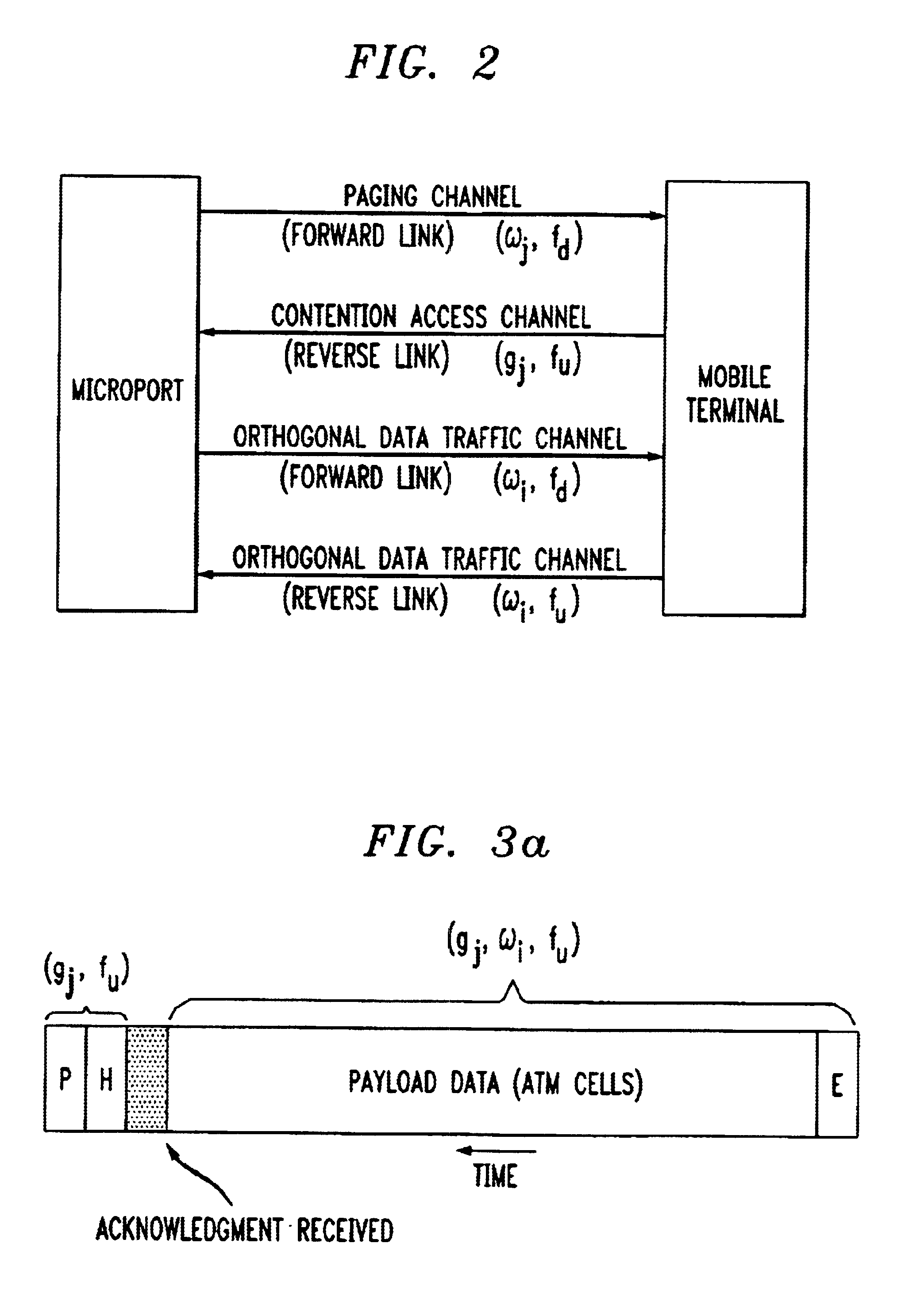
[0007]The present invention relies upon the application by a source user terminal of an individual spreading code (PN-code) based on a port identifier to a transmission signal (containing no payload data). This forms the preamble. A few bits of data follow, to which the PN-code is also applied to form the packet header. Following the preamble and packet header, a switch is triggered and PN-code sequences are applied by the source user terminal, after applying an individual spreading code based on an identifier for an individual user, to a transmitted spread spectrum signal (containing individual user data). The transmitted spread spectrum signal is received by an originating access radio port (also called the receiving microport because the microport receives information and data from a mobile subscriber) to distribute the spread spectrum signal to the intended destination radio port (also called the transmitting microport because the microport transmits information and data to the mobile subscriber) via a wireline packet-switched network such as ATM. The packet-switched network is used to distribute information and data to the destination radio port. Switching complexity and equipment volume are thereby greatly reduced since all user code processing is performed at the periphery of the network (subscriber / user terminal) and greater data rates and improved system performance can be realized.
[0009]It is therefore an objective of the present invention to simplify and reduce switching complexity (hardware and / or software) and equipment volume within the infrastructure of a terrestrial CDMA wireless system satellite to increase system performance and data rates.
[0010]Yet another object of the present invention is to provide a method and apparatus for improving radio port routing of spread spectrum user data within a terrestrial CDMA wireless system using a packet-switched network backbone.
[0011]It is another objective of the present invention to take advantage of CDMA orthogonal coding schemes to perform baseband self-routing (at the originating wireless terminal) in an effort to reduce the volume of radio port switching equipment to the number of interconnected radio ports rather than the number of individual system users.

Problems solved by technology

The difficulty in a terrestrial system is the inherent need for internal communication.
Packet switching affords flexibility in the bandwidth assigned to a Message switching and circuit switching would not appear to offer the flexibility and speed necessary to meet the demands of multimedia.
Datagrams also do not appear to be a solution to the problems because of the additional circuitry and overhead involved in datagram reassembly.
This method reduces optimum system performance and data rates.

Method used


Image

  • CDMA to packet-switching interface for code division switching in a terrestrial wireless system
  • CDMA to packet-switching interface for code division switching in a terrestrial wireless system
  • CDMA to packet-switching interface for code division switching in a terrestrial wireless system

Examples


Embodiment Construction

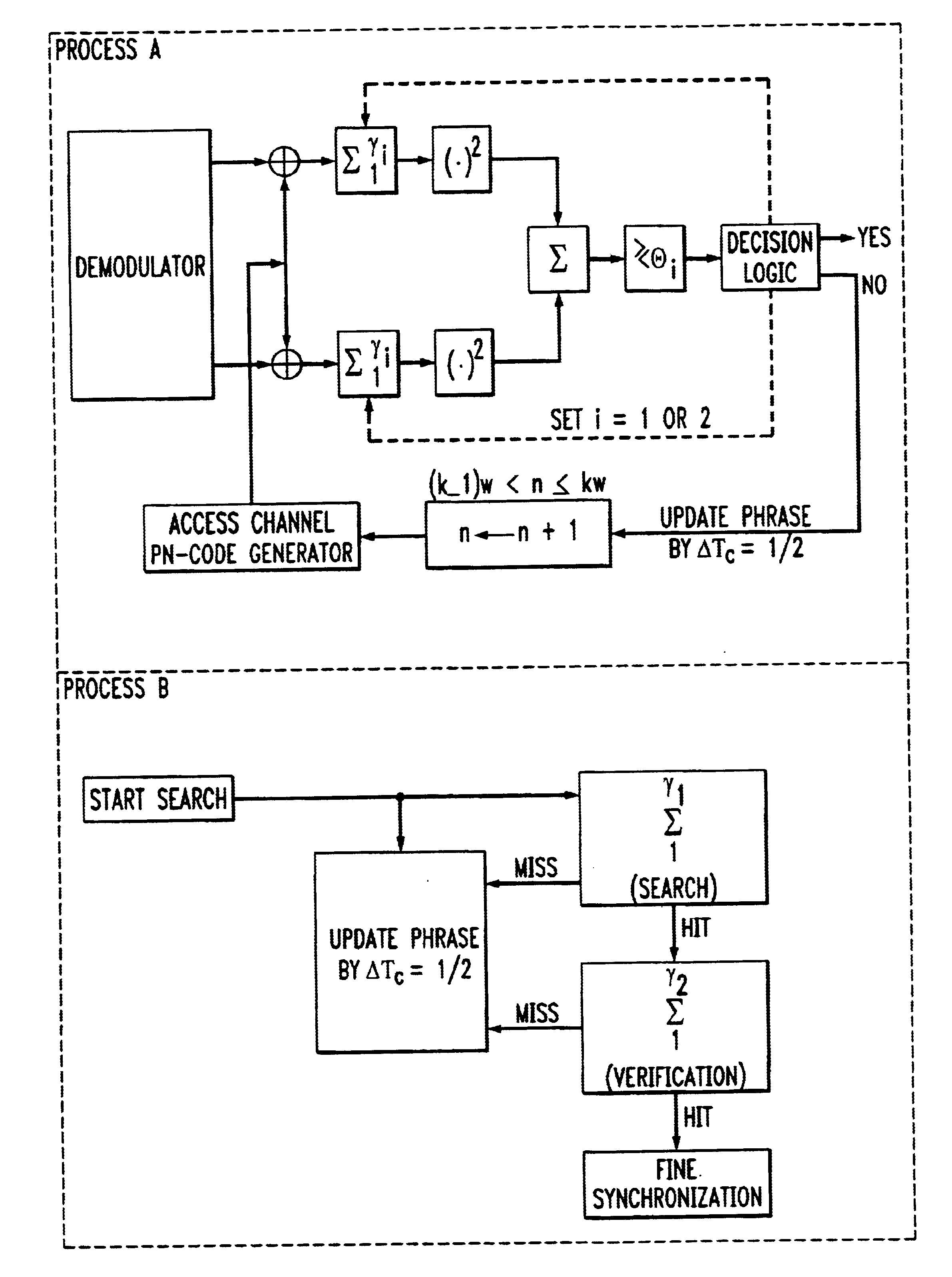
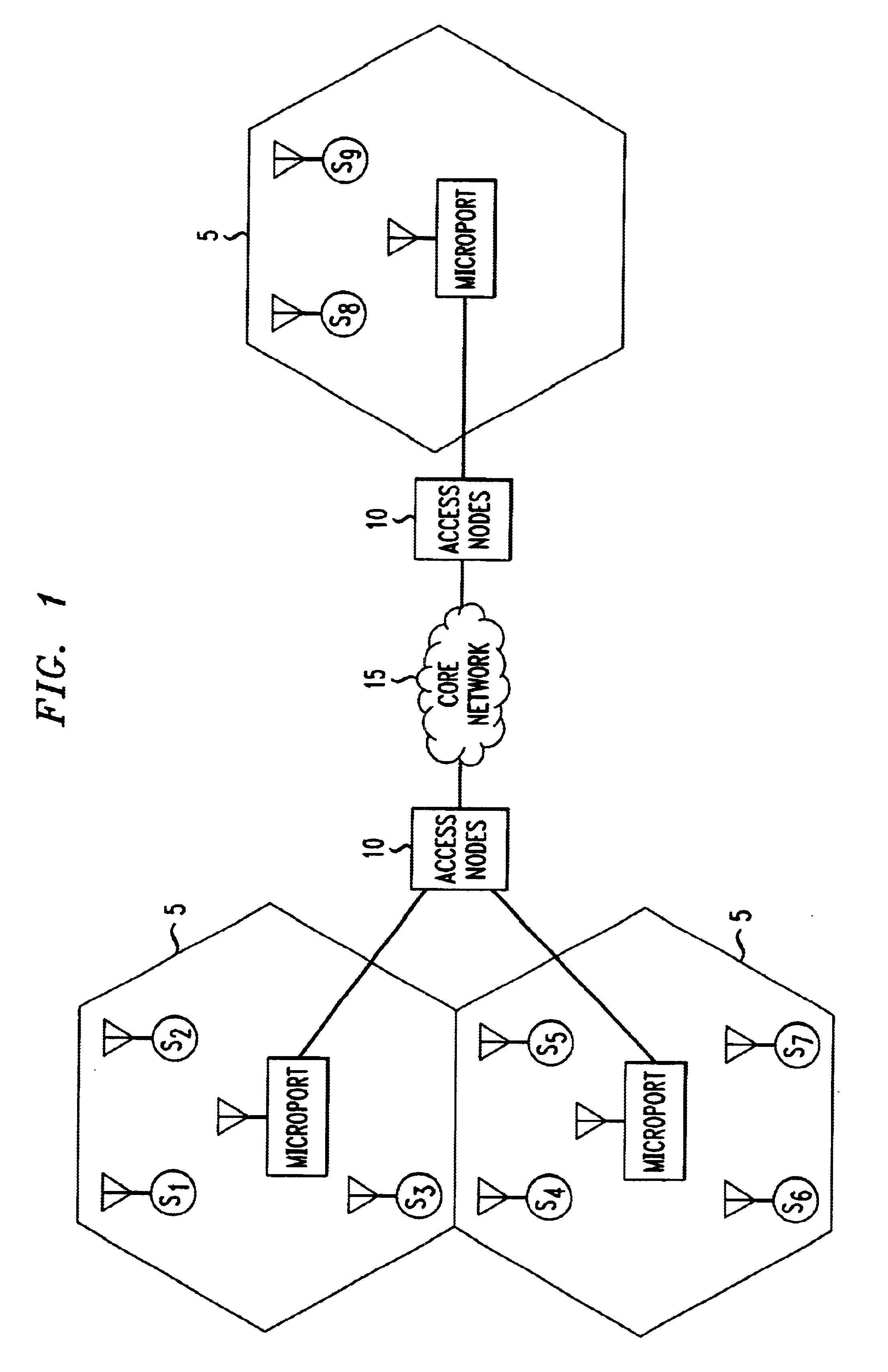
[0033]FIG. 1 depicts a terrestrial wireless system configuration. Within a terrestrial CDMA wireless communications system interfacing with a plurality of originating and destination wireless terminal users, a core network backbone 15 interconnects a plurality of access nodes 10 within the system. Originating wireless subscriber / user terminals and destination wireless subscriber / user terminals are interchangeable. That is, on any given transmission, a given wireless subscriber / user terminal may be an originating or a destination terminal. The wireless subscriber / user terminals are depicted within cells 5 by a circle with an antenna. They are distinguished from one another by the letter “S” with a numerical subscript. It should be noted here that the number and identification of subscriber / user terminals within a cell will vary as subscribers drive through a given cell. Also depicted within each cell is an access radio port (also called a microport). An access radio port is depicted ...


PUM


Abstract

A low-cost, flexible, high performance system and method comprises a means for interfacing a code division wireless system to a fast packet-switched network for transmission over a core network to a destination terminal user via a destination access node and a destination access radio port. The method is for code division switching at an originating terminal, the originating terminal being located within a microport cell of a terrestrial wireless network at a given instant in time, where said network interfaces with an access radio port, and comprises the steps of spreading a transmission signal by a PN-code assigned to an intended receiving port, inserting an identifier of a few bits for identifying a user, spreading a payload data signal by an orthogonal code, spreading the orthogonal spread payload data signal by the PN-code associating the user with payload data, modulating the PN-code spread transmission signal and the twice-spread payload data signal, and forwarding the modulated PN-code spread transmission signal and the modulated twice-spread payload data signal to an access radio port. The code division switching system at an originating terminal is described, the originating terminal being located within a microport cell of a terrestrial wireless network at a given instant in time, where said network interfaces with an access radio port, comprises a first spreader for spreading a transmission signal by a PN-code assigned to an intended receiving port, a second spreader for spreading a payload data signal by an orthogonal code assigned to a receiving terminal user to which the payload data signal is directed, the payload data signal being further spread by the first spreader, a means for forwarding the PN-code spread transmission signal to an access radio port and a means for forwarding the twice-spread transmission signal to an access radio port.

Description

[0001]This application is related by subject matter to U.S. patent application Ser. No. 09 / 770,890, filed Jan. 26, 2001, entitled “Method For CDMA To Packet-Switching Interface For Code Division Switching In A Terrestrial Wireless System”.FIELD OF THE INVENTION[0002]The invention relates generally to communications systems and in particular, to wireless systems using a wireline backbone to communicate between a source subscriber terminal and a destination subscriber terminal, where the wireline backbone forms a core network.BACKGROUND OF THE INVENTION[0003]The difficulty in a terrestrial system is the inherent need for internal communication. Cells are generally not connected over the air. Instead, an air interface is defined within a small area around a base station (access radio port or microport). A number of microports are distributed geographically to give a desired region of coverage (e.g., the continental US). The distributed microports are connected by a plurality of access ...

Claims


Application Information

Patent Timeline
Patent Type & Authority Patents(United States)
IPC IPC(8): H04L1/16H04L1/18H04L12/56H04Q11/04H04B1/707H04W8/26H04W28/04H04W88/02
CPCH04L1/1803H04Q11/0478H04B1/707H04L2012/5607H04W88/02H04W8/26H04W28/04H04L2012/5676
Inventor GERAKOULIS, DIAKOUMIS PARISSIS
Owner AMERICAN TELEPHONE & TELEGRAPH CO
Learn More