Cooling structure for cooling vehicle electronic unit

a technology for electronic units and cooling structures, applied in domestic cooling apparatus, roofs, lighting and heating apparatus, etc., can solve problems such as failure of electronic units, achieve the effects of reducing design changes, facilitating heat radiation of vehicle electronic units, and effective restricting condensed water

Inactive Publication Date: 2005-07-05
DENSO CORP
View PDF6 Cites 8 Cited by
  • Summary
  • Abstract
  • Description
  • Claims
  • Application Information

AI Technical Summary

Benefits of technology

[0007]In view of the above-described problems, it is a first object of the present invention to provide a cooling structure capable of cooling a vehicle electronic unit while effectively restricting condensed water from being generated on the vehicle electronic unit.
[0008]It is a second object of the present invention to provide a module structure of vehicle cockpit components capable of reducing its design change.
[0009]According to a first aspect of the present invention, a cooling structure for cooling a vehicle electronic unit includes an air conditioning case for defining an air passage through which air flows into a passenger compartment of the vehicle, a blower for blowing air introduced from at least one of an inside-air introduction port and an outside-air introduction port of the air conditioning case into the passenger compartment, and a cooling heat exchanger disposed in the air conditioning case for cooling air blown by the blower. In the cooling structure, the air conditioning case has a cooling opening at a position upstream from the cooling heat exchanger, and the cooling opening is provided in the air conditioning case such that air including at least inside air is blown from the cooling opening to the electronic unit by the blower. Accordingly, heat radiation of the vehicle electronic unit can be facilitated by the blower of the vehicle air conditioner. Therefore, an electronic unit having low-thermal resistance can be adopted, and cost of the vehicle electronic unit can be reduced. Furthermore, because only the air including inside air, without being cooled by the cooling heat exchanger, is blown to the electronic unit. Therefore, the electronic unit can be prevented from being excessively cooled, and the surface temperature of the vehicle electronic unit can be restricted from reducing less than the dew point. Thus, it can effectively restrict condensed water from being generated on the electronic unit.
[0010]Preferably, the inside-air introduction port is constructed of first and second inside-air introduction ports, and the air conditioning case has a partition member for partitioning the air passage into a first air passage through which air from the first inside-air introduction port and the outside-air introduction port flows into the passenger compartment, and a second air passage through which air from the second inside-air introduction port flows to the electronic unit and the passenger compartment. For example, the blower includes a first fan disposed in the first air passage, and a second fan disposed in the second air passage. In this case, only inside air can be introduced to the vehicle electronic unit. Therefore, it can prevent the vehicle electronic unit from being excessively reduced in the winter.
[0011]According to a second aspect of the present invention, a module structure of vehicle cockpit components includes: a function module assembly formed by modularizing an air conditioning unit and a peripheral member of the air conditioning unit, the air conditioning unit being for adjusting an air temperature and for blowing the adjusted air into a passenger compartment of the vehicle; a structure module assembly formed by modularizing a steering support member for supporting a steering shaft, and the air bag unit for protecting a passenger in a vehicle collision; and a design module assembly formed by modularizing a dashboard and at least one of a display unit and a meter unit in the vehicle. Accordingly, the vehicle cockpit components are divided into at least three module assemblies of the function module assembly, the structure module assembly and the design module assembly. Therefore, it is possible to change only the design of the design module assembly for every vehicle grade, and the same design of the function module assembly and the same design of the structure module assembly can be commonly used for many vehicle grades. Further, in some cases, only the design of the design module assembly and the design of the structure module assembly can be changed for every vehicle type, and the function module assembly can be commonly used for many vehicle types. Thus, the module structure of the vehicle cockpit components is constructed so as to simplify its design change. Further, the vehicle cockpit components such as the display unit, the meter unit, the dashboard, the steering support member, the air bag unit, the air conditioning unit and its peripheral part are divided into the above three module assemblies. Therefore, in the vehicle assembly line, assembly time can be reduced as compared with a case where the vehicle cockpit components are assembled to a vehicle one by one.

Problems solved by technology

Therefore, the electronic unit may fail, and may be short-circuited, for example.

Method used


Image

  • Cooling structure for cooling vehicle electronic unit
  • Cooling structure for cooling vehicle electronic unit
  • Cooling structure for cooling vehicle electronic unit

Examples


first embodiment

[0029](First Embodiment)

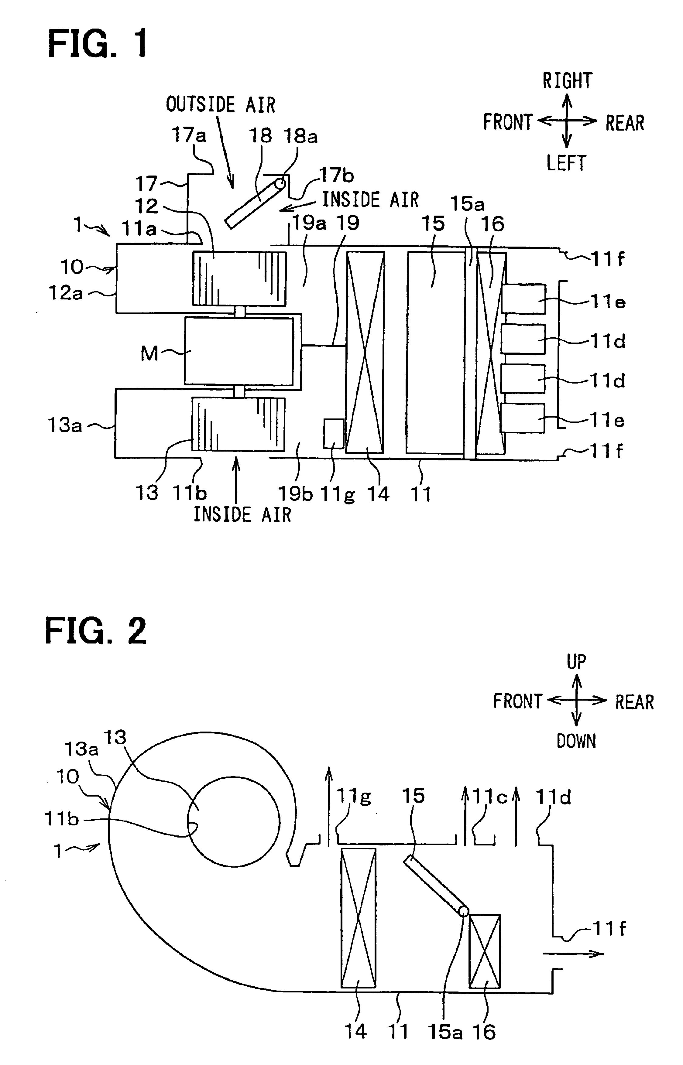
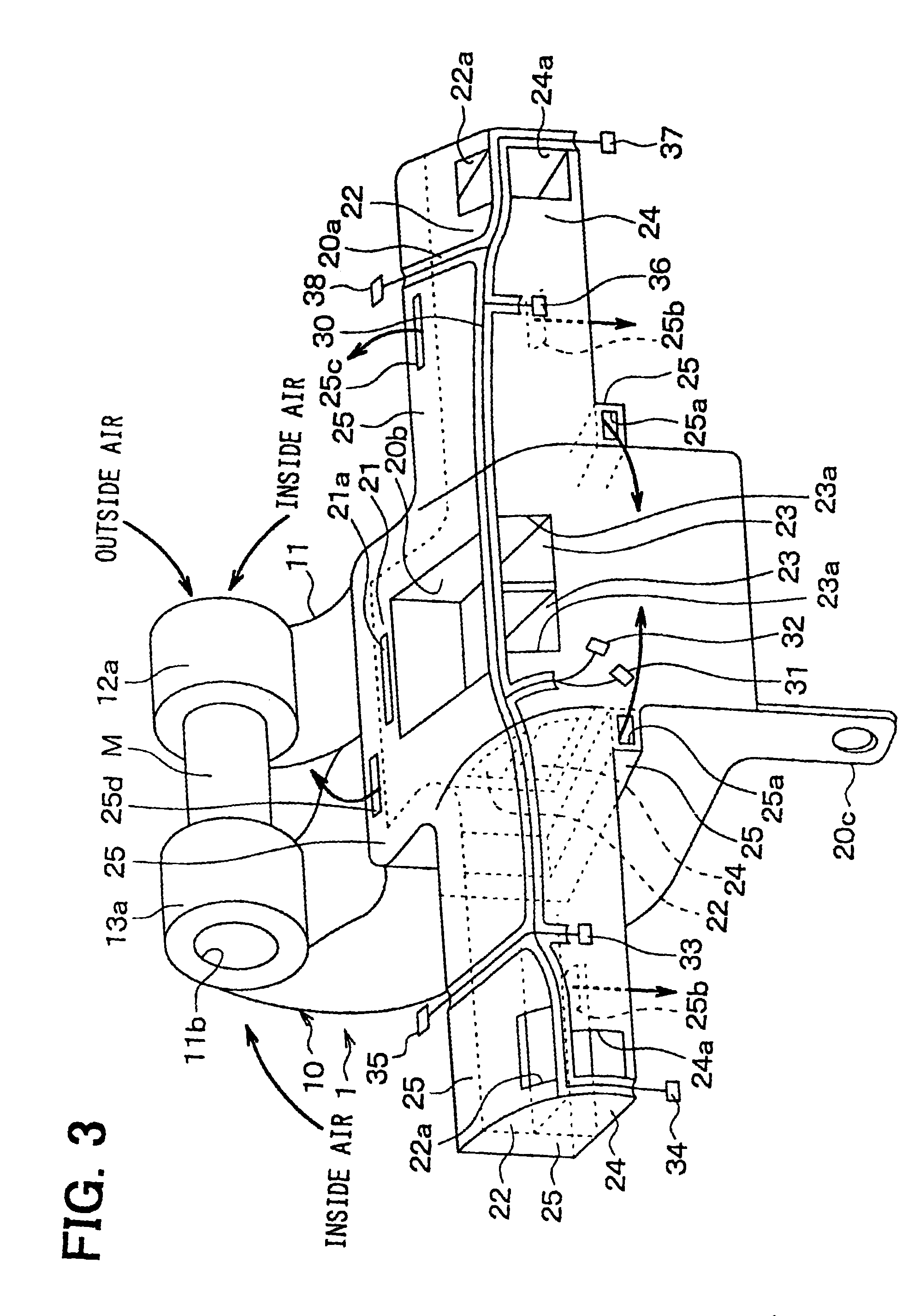
[0030]The first embodiment of the present invention will be now described with reference to FIGS. 1-6. In the first embodiment, a vehicle air conditioner 1 includes an interior unit 10 shown in FIGS. 1, 2. The interior unit 10 is disposed inside a dashboard positioned on a front side in a passenger compartment, substantially at a center area in a vehicle right-left direction. The vehicle air conditioner 1 is mounted in a vehicle in the arrangement of FIGS. 1, 2 in the vehicle right-left direction, in a vehicle front-rear direction and in a vehicle up-down direction. The interior unit 10 of the vehicle air conditioner 1 is constructed with a blower unit and an air conditioning unit. The blower unit includes a blower and the like, and the air conditioning unit includes a heat exchanger and the like. The blower unit and the air conditioning unit are integrated to each other to construct the interior unit 10. The interior unit (air conditioning unit) 10 includes ...

second embodiment

[0051](Second Embodiment)

[0052]The second embodiment will be now described with reference to FIGS. 7-9. In the second embodiment, vehicle cockpit components are modularized to form a function module assembly M1, a structure module assembly M2 and a design module assembly M3. In the second embodiment, the module assemblies M1-M3 are mounted on a vehicle in the arrangement in FIGS. 7-9 in the vehicle front-rear direction, in the vehicle right-left direction and in the vehicle up-down direction.

[0053]As shown in FIG. 7, peripheral members 200, 210, 220 are integrally attached to the interior unit 10 (air conditioning unit) to form the function module assembly M1. In the second embodiment, the interior unit 10 has a structure similar to that in FIG. 1 in the above-described first embodiment. Specifically, the peripheral member 200 is a case for containing an electronic control unit, the peripheral member 210 is a junction box, and the peripheral member 220 is an integrated wiring bundle...

third embodiment

[0063](Third Embodiment)

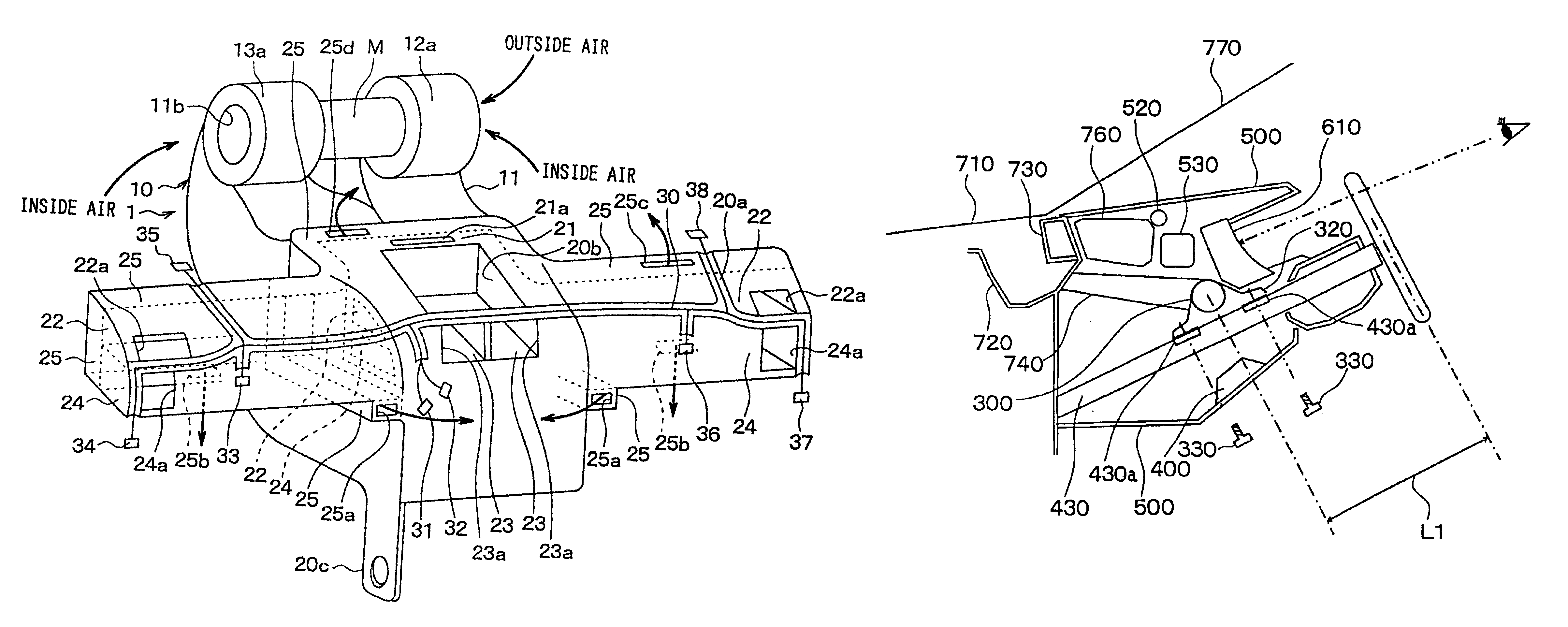
[0064]The third embodiment will be now described with reference to FIGS. 10, 11A, 11B. In the above-described second embodiment, the steering shaft 430 is inserted into an insertion hole provided in the steering support member 300 so as to be supported by the steering support member 300. Further, the steering support member 300 constructs the design surface 310 of the lower dashboard. In the third embodiment, as shown in FIGS. 11A and 11B, a portion of the steering support member 300, for supporting the steering shaft 430, is located below the steering shaft 430. Further, the steering support member 300 is disposed above the dashboard part 500 in invisible from the inside of the passenger compartment. The steering support member 300 is provided in a shape of a pipe extending in the vehicle right-left direction.

[0065]The steering support member 300 includes a bracket 320 for supporting the steering shaft 430. A fastening portion 430a of the steering shaft 430 ...


PUM


Abstract

A vehicle air conditioner includes an air conditioning case, a blower fan for blowing conditioned air into a passenger compartment, and an evaporator disposed in the air conditioning case. The air conditioning case has a cooling opening upstream from the evaporator, so that at least inside air is blown by the blower fan to vehicle electronic units through the cooling opening. Thus, heat radiation of the electronic units can be facilitated by air blown from the blower fan. Further, because at least inside air, without being cooled by the evaporator, is blown to the electronic units, the electronic units can be prevented from being excessively cooled. Accordingly, it can restrict the surface temperature of the electronic units from reducing less than a dew point, thereby effectively reducing condensed water on the electronic units.

Description

CROSS-REFERENCE TO RELATED APPLICATION[0001]This application is related to and claims priority from Japanese Patent Applications No. 2002-253965 filed on Aug. 30, 2002, No. 2002-311262 filed on Oct. 25, 2002, and No. 2003-80414 filed on Mar. 24, 2003, the contents of which are hereby incorporated by reference.BACKGROUND OF THE INVENTION[0002]1. Field of the Invention[0003]The present invention relates to a cooling structure for cooling a vehicle electronic unit, and a module structure of vehicle cockpit components.[0004]2. Description of Related Art[0005]Generally, an electronic member having a high thermal resistance is used for a heat-generation electronic unit such as an integrated circuit (IC) chip mounted in a vehicle. Alternatively, a heat sink or a cooling fan is provided to only cool the heat-generation electronic unit. The electronic unit maybe cooled by air blown from a vehicle air conditioner. However, if the air from the vehicle air conditioner is simply blown to the ele...

Claims


Application Information

Patent Timeline
Patent Type & Authority Patents(United States)
IPC IPC(8): B60H1/00
CPCB60H1/00514B60H2001/00614
Inventor TANAKA, HISASHIIKUTA, HARUKIITO, KOICHI
Owner DENSO CORP
Why Eureka
Try Eureka