Precipitation resistant ridge vent

a ridge vent and precipitation resistance technology, which is applied in the field of roof vents, can solve the problems of fiber mats, increasing the cost and complexity of roof vent construction, and general deterioration of foam products, so as to achieve convenient manufacture and easy installation

Inactive Publication Date: 2005-07-05
LIBERTY DIVERSIFIED INDS
View PDF32 Cites 39 Cited by
  • Summary
  • Abstract
  • Description
  • Claims
  • Application Information

AI Technical Summary

Benefits of technology

[0016]The present invention largely solves the above problems by providing a shingle over ridge vent that effectively excludes the entry of precipitation and foreign matter into the roof space. The ridge vent is sturdy, easily manufactured and readily installed. In addition, the filtering material that excludes precipitation is protected from factors that speed its deterioration.
[0018]The material is cut and scored so that it may be folded to have a single top panel extending its entire length. At either side of and below the top panel a plurality of folds create a plurality of stacked layers of the corrugated material with a plurality of airflow passages therethrough. A routed groove may extend the length of the bottom side of the top panel of the ridge vent to facilitate bending the ridge vent to conform to different roof pitches and to provide an additional exit path for air flowing out of the ridge vent.
[0020]The enclosure of the filtering fabric inside the ridge vent protects the fabric from exposure to sunlight and other factors that encourage deterioration.

Problems solved by technology

However, without protection of the ventilating openings, wind blown precipitation, debris and insects enter the roof and encourage damage to the structure through mildew, rot and infestation.
Foam products, in general, tend to deteriorate with age and exposure to the elements.
Fiber mats may suffer from compression, for example, under a snow load, and add expense and complexity to the construction of roof vents.
Check valves have moving parts and are prone to the possibility of wear and blockage and when they operate ventilation is restricted.
They also complicate the manufacturing process.
The installation of wind deflectors requires an additional step in the installation process with an attendant increase in time and expense.
Considerable complexity is added to the manufacturing process in order to incorporate the flashing into the vent.
The presence of a rigid or semi rigid flashing may also prevent or complicate the rolling of the vent for transport and reduce ease of application.
Sun and wind may accelerate its deterioration.

Method used


Image

  • Precipitation resistant ridge vent
  • Precipitation resistant ridge vent
  • Precipitation resistant ridge vent

Examples


Embodiment Construction

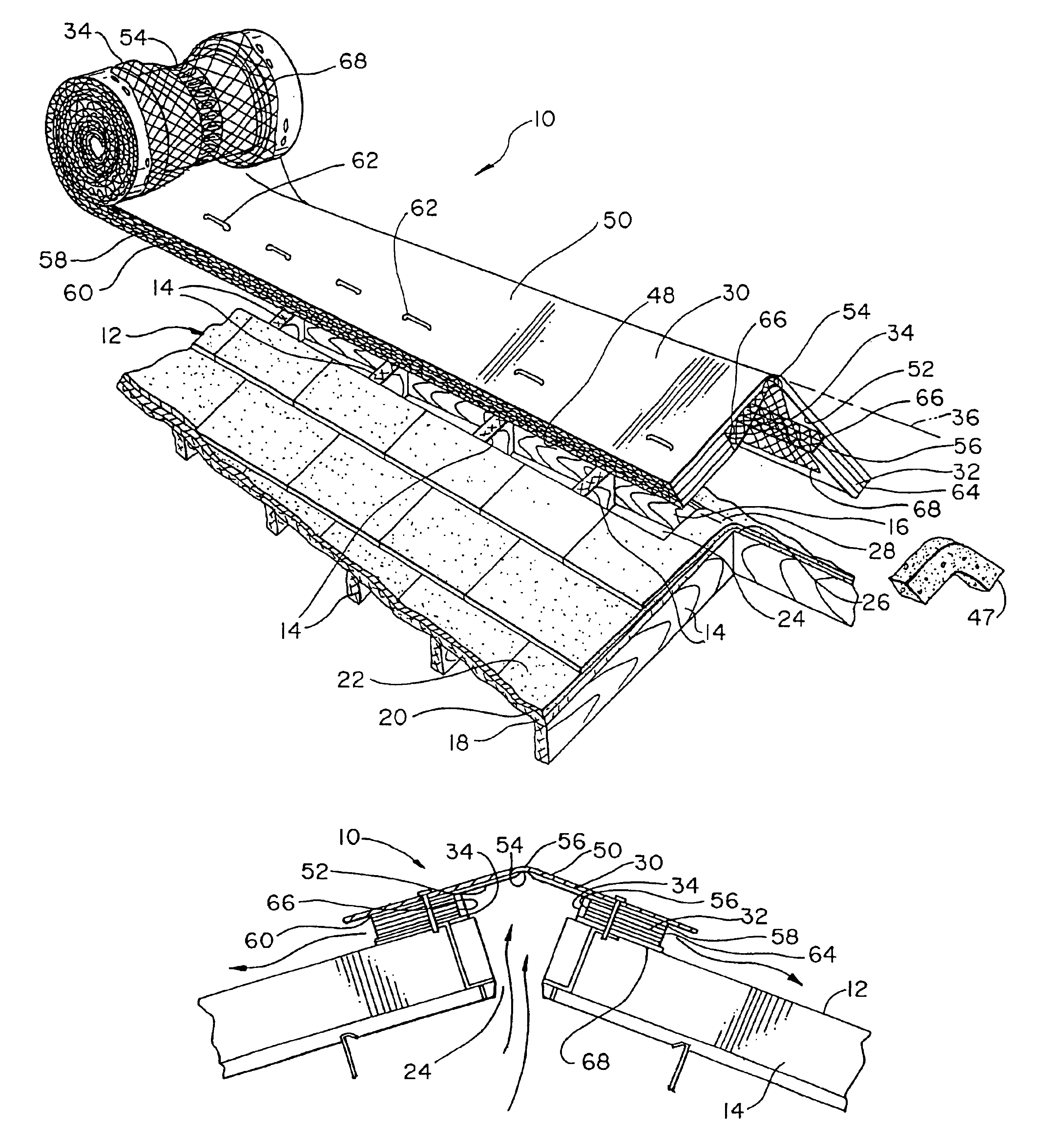
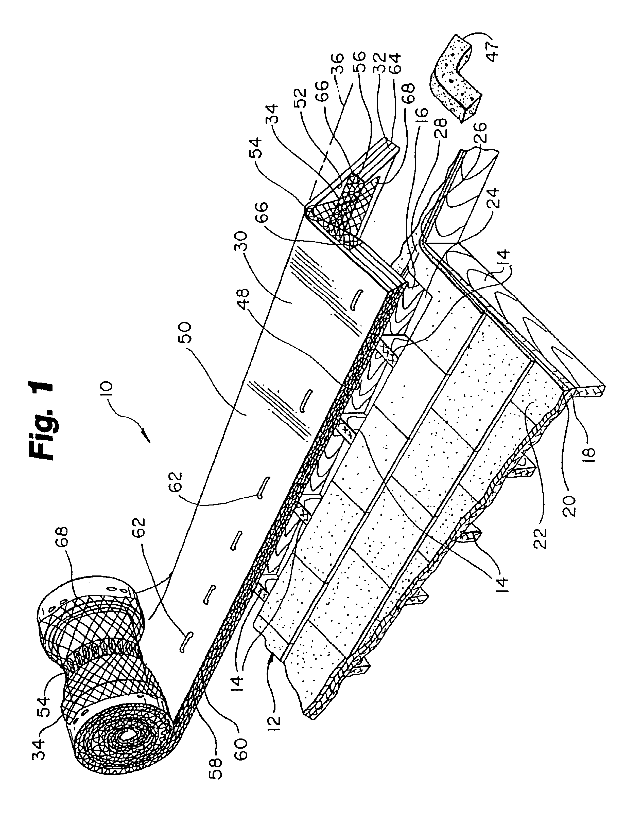
[0034]FIG. 1 depicts the precipitation resistant ridge cap roof vent 10 being installed on a roof 12. The roof depicted is a rafter roof, though the ridge vent 10 may be installed on many other types of roofs to provide ventilation. The roof 12 depicted includes rafters 14 secured to a ridge board 16. Rafters 14 support sheathing 18. Sheathing 18 may be of plywood, oriented strand board, planks or other suitable material secured to rafters 14. Generally sheathing 18 is overlaid with tarred felt paper 20 which is in turn overlaid with shingles 22, though other roofing materials may be employed. A cutout slot 24 is provided along the ridge 26. Slot 24 may terminate some distance from the end 28 of the ridge 26.

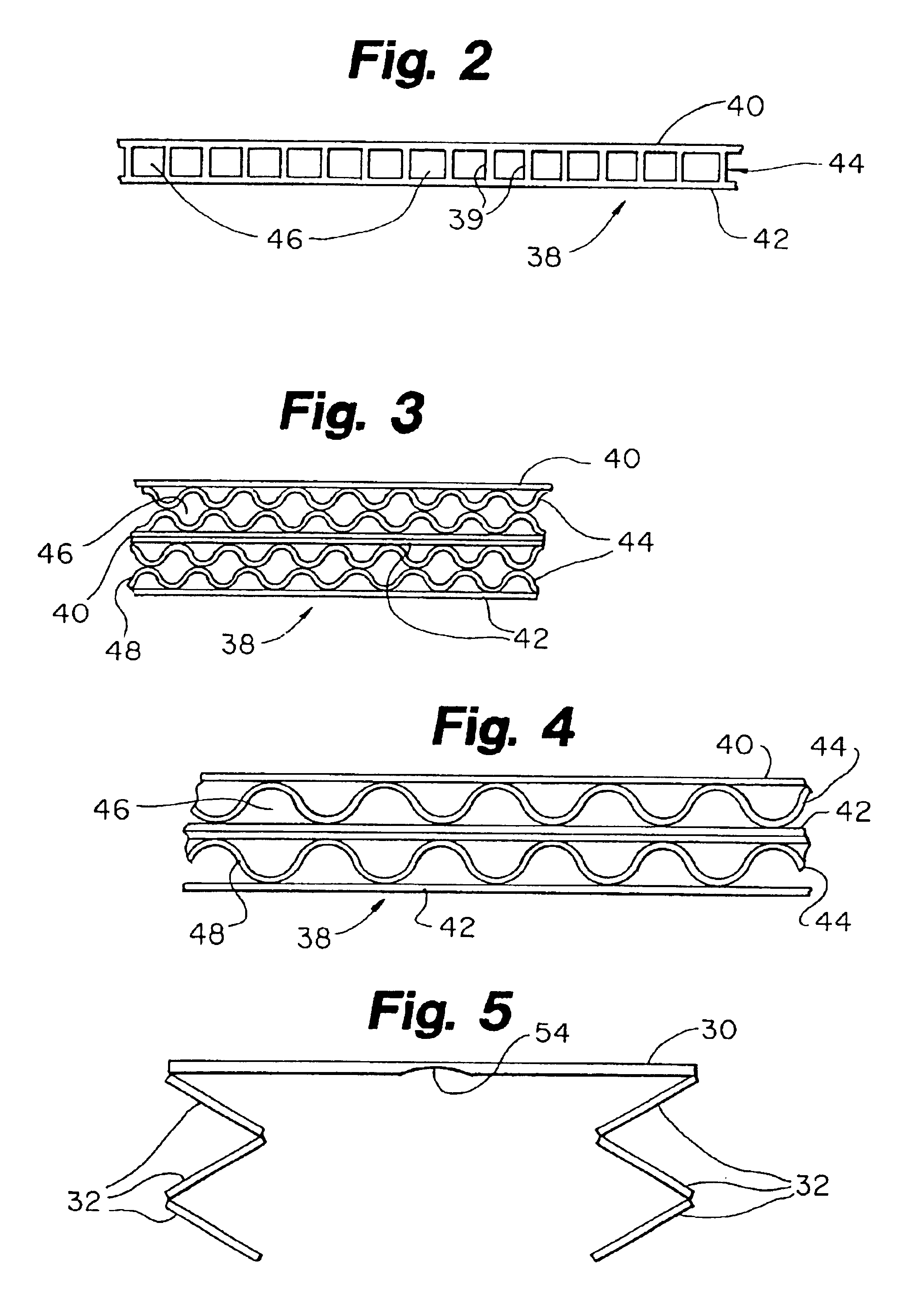
[0035]The ridge vent 10, as depicted in FIGS. 1, 5, 6, and 7, broadly includes a top panel 30, a plurality of vent panels 32 and filtering fabric 34. Top panel 30 presents a long axis 36 aligned generally parallel with the ridge 26 of the roof 12 when ridge vent 10 is installed....


PUM

PropertyMeasurementUnit
areaaaaaaaaaaa
adhesiveaaaaaaaaaa
air permeableaaaaaaaaaa

Abstract

A precipitation resistant ventilator for a structure enclosing an interior space. The ventilator encloses a space that is in communication with the structure interior space. A thin sheet of air permeable water resistant material is disposed within the ventilator interior. The thin sheet of air permeable water resistant material forms a barrier that excludes the entry of precipitation and other foreign matter into the roof structure while still allowing air exchange.

Description

RELATED APPLICATION[0001]This application is a continuation of application Ser. No. 10 / 209,851 filed Jul. 31, 2002 now U.S. Pat. No. 6,623,354 and application Ser. No. 09 / 651,071 filed Aug. 30, 2000 now U.S. Pat. No. 6,450,882.FIELD OF THE INVENTION[0002]The present invention relates to roof ventilators folded from a blank of corrugated plastic sheet material having a top panel and two vent panels. More particularly, it relates to a roof vent of corrugated construction including an internal filtering material to exclude precipitation, debris and vermin from entry into the vented roof.BACKGROUND OF THE INVENTION[0003]It is a common practice in the construction of structures to ventilate gable roofs by providing a vent along the roof ridge. Ventilation apertures are formed in the construction process by leaving or cutting an open slot along the ridge through the sheathing material covering the roof. Heated air rises and escapes at the ridge taking with it moisture that may have accumu...

Claims


Application Information

Patent Timeline
Patent Type & Authority Patents(United States)
IPC IPC(8): E04D13/00E04D13/17
CPCE04D13/176Y10T29/49826Y10T29/49623
Inventor MORRIS, RICHARD J.VANWEY, SCOTT CHARLES
Owner LIBERTY DIVERSIFIED INDS
Why Eureka
Try Eureka