Artificial disc

a technology of artificial discs and implants, applied in bone implants, medical science, prosthesis, etc., can solve the problems of spinal segment immobilization, complex operation required, and increased trauma, and achieve the effect of improving the stability and stability of the spinal segmen

Inactive Publication Date: 2005-07-05
BIORTHEX
View PDF17 Cites 82 Cited by
  • Summary
  • Abstract
  • Description
  • Claims
  • Application Information

AI Technical Summary

Benefits of technology

[0042]Thermal shock SHS: In this process, the thermal shock is performed by heating a mixture of various powders up to the temperature at which the self supported chemical react

Problems solved by technology

The disadvantage of this device is its structural complexity and accompanying increased traumatism, the complexity of the operation required, and the high rigidity that results in the immobilization of the spinal segment.
The disa

Method used


Image

  • Artificial disc
  • Artificial disc
  • Artificial disc

Examples


example

[0048]The possibility of achieving the stated technical outcome is illustrated by a test case of the clinical trial use of the implant in the Regional Clinical Hospital (RCH) of the City of Novosibirsk (case no. 2-3576).

[0049]Male patient D., 45 years old, was treated in the Department of Neurosurgery of RCH for discogenic myelopathy, medial hernia of disk C6-C7, and tetraparesis.

[0050]Computer tomography confirmed posterior medial hernia of the disk C6-C7.

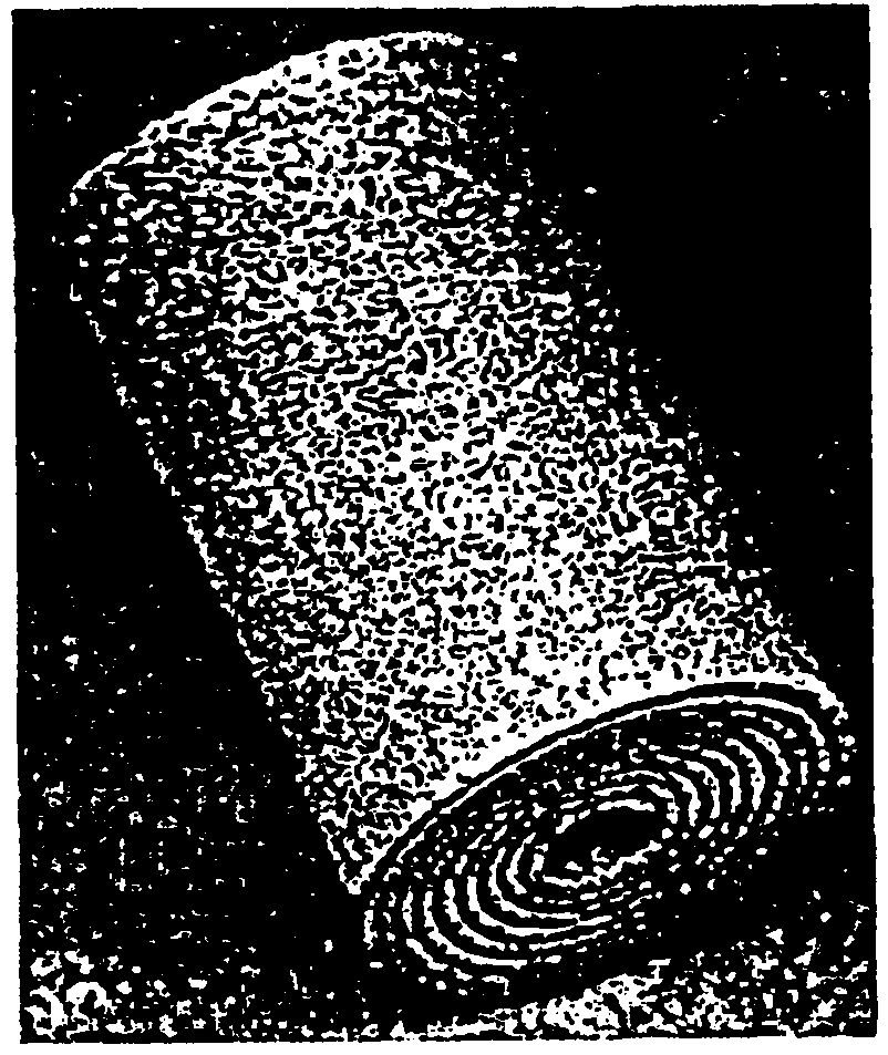
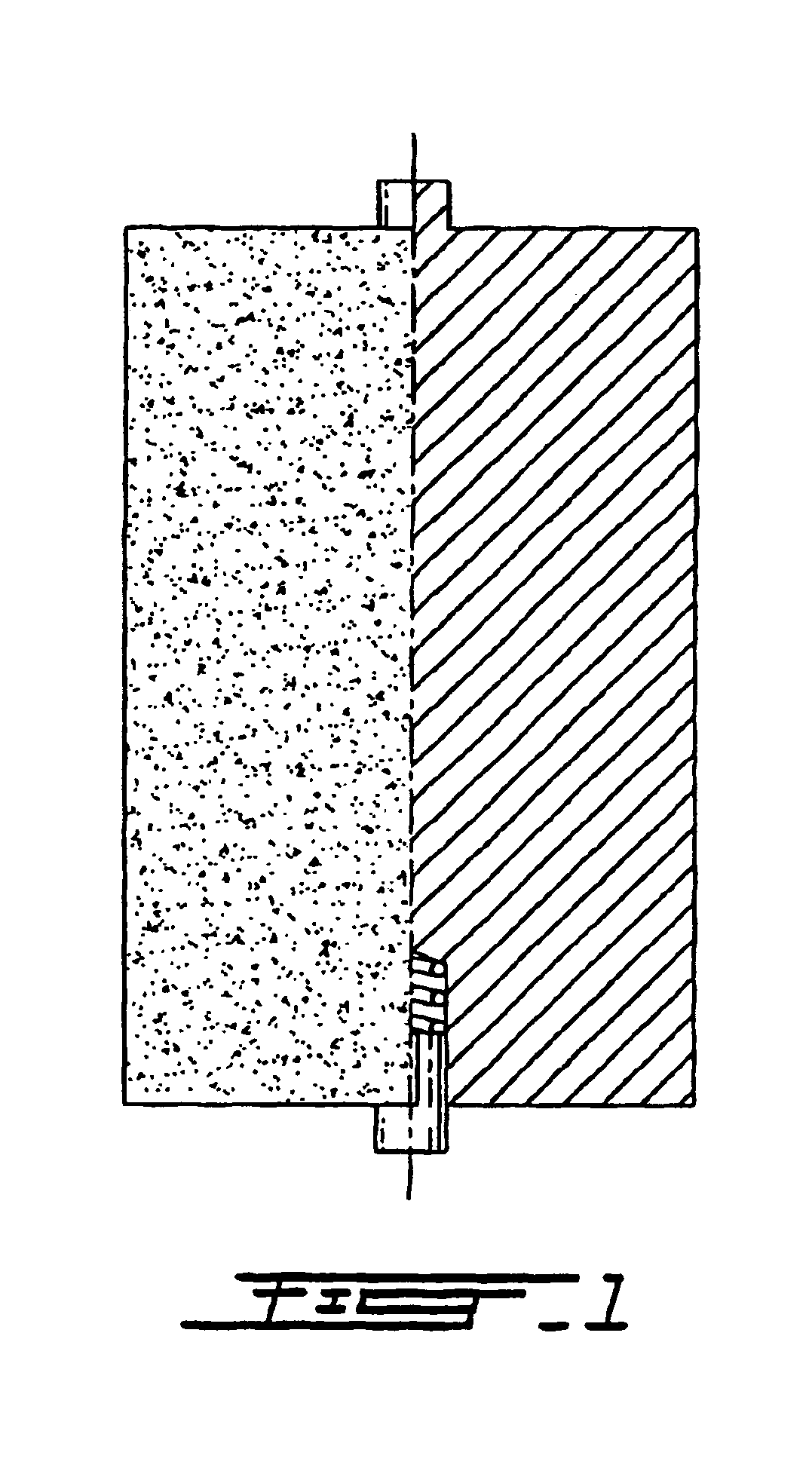
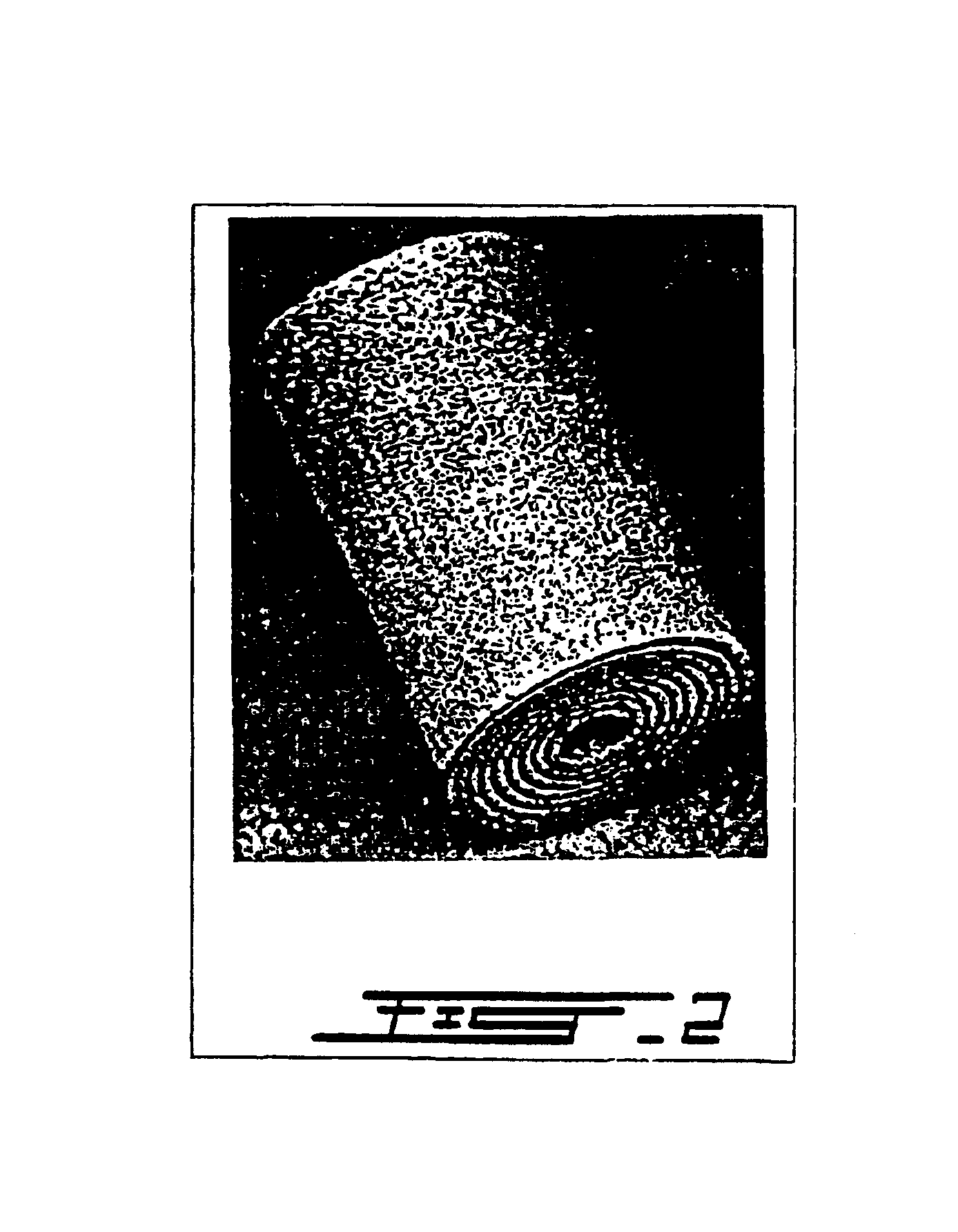
[0051]The patient underwent surgery for anterior interbody spondylodesis using the device of the invention. The device made of porous superelastic TiNi alloy in the shape of a rolled sheet (FIG. 2) with the following dimensions was used: length of the device 20 mm, diameter 18 mm, thickness of the sheet 0.4 mm, opening between the layers 0.2 mm.

[0052]The device was used in the following way. After total C6-C7 discectomy, a medial interbody socket with a diameter of 17 mm was created in the bodies of vertebrae C6-C7.

[0053]The devic...


PUM


Abstract

An implant device for surgical treatment of spinal disc damage or injury is formed as a resilient body comprising porous TiNi; the body is internally mobile such that it resiliently expands and contracts in response to variation in forces applied externally on the body.

Description

TECHNICAL FIELD[0001]The invention relates to a medical implant device for use in the surgery of the spine.BACKGROUND ART[0002]Traumas or diseases of the spine result in damage to individual vertebrae, intervertebral discs, or combinations thereof Different techniques are used for the surgical treatment, according to the indications, among which is the prosthesis of lost or removed fragments and their stabilization within the spinal column, otherwise called spondylodesis in surgical practice.[0003]It is desirable to develop new and improved technical devices for spinal surgery providing improved functional attributes, increase of success rate, and the further extension of their applications.[0004]Existing approaches include a technique of posteriorspondylodesis [1. Russian Patent 2,076,6541] employing a device consisting of a set of supporting implants that are cylindrical in shape, a stratified implant, and a bracing device, the brace is made of TiNi alloy with thermomechanical sha...

Claims


Application Information

Patent Timeline
IPC IPC(8): A61F2/44A61F2/00A61F2/30A61F2/02
CPCA61F2/442A61F2002/30013A61F2002/30224A61F2002/30293A61F2002/30563A61F2002/30565A61F2002/30668A61F2002/30769A61F2230/0069A61F2230/0091A61F2250/0001A61F2250/0024A61F2310/00023A61F2002/30011
Inventor GJUNTER, VICTOR EDUARDOVICH
Owner BIORTHEX
Why Eureka
Try Eureka