Multiple wavelength pumping of raman amplifier stages

a technology of amplifier stage and amplifier stage, which is applied in the field of broadband sagnac raman amplifier and laser, can solve the problems of not being cost-effective without optical amplifiers, major difficulties in upgrading to the higher bandwidth edfa technology, and not being able to permit further upgrading based on wavelength-division multiplication, so as to improve noise performance and protect against double rayleigh scattering

Inactive Publication Date: 2005-07-05
XTERA COMM
View PDF54 Cites 6 Cited by
  • Summary
  • Abstract
  • Description
  • Claims
  • Application Information

AI Technical Summary

Benefits of technology

[0027]Second, turn-key operation is obtained by minimizing the need for polarization controllers through use of a polarization maintaining cavity. In one embodiment, the Sagnac loop mirror of the broadband Sagnac Raman amplifier is fabricated from polarization maintaining fiber cross-spliced at the middle of the loop mirror. In another embodiment, the Sagnac loop mirror is made of polarization maintaining fiber and the Raman gain fiber is separated from the Sagnac loop mirror. Input and output ports of the amplifier are polarization maintaining WDMs.
[0028]Third, the noise performance is improved and protection against double Rayleigh scattering is provided by using a polarization diversity pumping system. In one embodiment of the polarization diversity pumping system, the pumping light is launched at a 45 degree angle into the polarization maintaining fiber to produce a beam having two polarization directions. Such angle is achieved by either rotating the fiber or using a quarter wavelength plate. In another embodiment, the pumping light is first divided by a 50:50 coupler into two beams. One beam travels through a retarder to change its polarization direction. Then a polarization beam splitter combines the two beams. In yet another embodiment, the polarization maintaining fiber is spliced at a 45 degree angle to the cladding-pumped fiber to output a beam having two polarization directions.

Problems solved by technology

Although WDM is critical in that it allows utilization of a major fraction of the fiber bandwidth, it would not be cost-effective without optical amplifiers.
Although EDFAs have had a significant impact in the past five years, they are not without problems.
This presents major difficulties in upgrading to the higher bandwidth EDFA technology.
However this approach does not permit further upgrading based on wavelength-division-multiplexing, and therefore is not seen as the best solution.
However, currently no glass formulation has proven to be commercially viable.
Aside from the wavelength mismatch, EDFAs are also inherently prone to signal loss when the pump laser fails.
Reliance on the “three-level” system could have catastrophic consequences for the reliability of fiber networks.
However, there is a significant problem with Raman amplifiers that has not heretofore been really overcome.
When Raman amplifiers are allowed to cascade through several orders, the pump source intensity fluctuations are combinatorially multiplied, and very rapidly result in enormous intensity fluctuations that have made systems virtually unusable.
All of these properties have lead most to conclude that stimulated Raman scattering amplifiers and cascade lasers are not suitable in general-purpose telecommunication applications.
However, as the temperature changes, the fiber birefringence changes and the mechanical setting of the PCs may also be perturbed.
As a result, the PCs may ruin the “turn-key” operation of the amplifier because they could require periodic readjustment with changing environmental conditions.
In the past attempts at applying Raman amplifiers to analog signal amplification, it was discovered that a major limitation arises from the noise associated with Double Rayleigh Scattering (DRS).
DRS refers to a second stimulated Rayleigh scattering event that scatters the backward traveling wave back into the original signal, thereby leading to interference with the original signal, cross-talk, and increased uncertainty of the amplitude (i.e., noise).
Therefore, the DRS noise source is a direct consequence of requiring high pump powers and long interaction lengths due to the inefficiency of the Raman amplification process.
Although this technique has been used for high gain EDFAs and in ring designs of Raman amplifiers, it increases the complexity and cost of the amplifier considerably due to the need for two additional WDMs and one isolator.

Method used


Image

  • Multiple wavelength pumping of raman amplifier stages
  • Multiple wavelength pumping of raman amplifier stages
  • Multiple wavelength pumping of raman amplifier stages

Examples


first embodiment

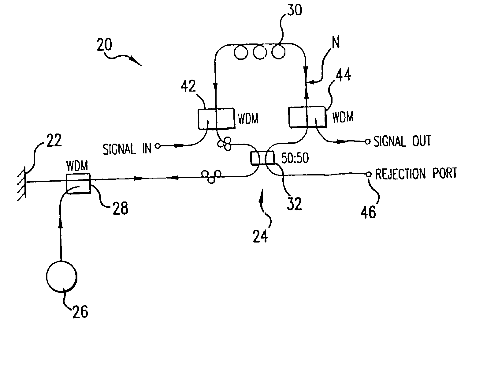
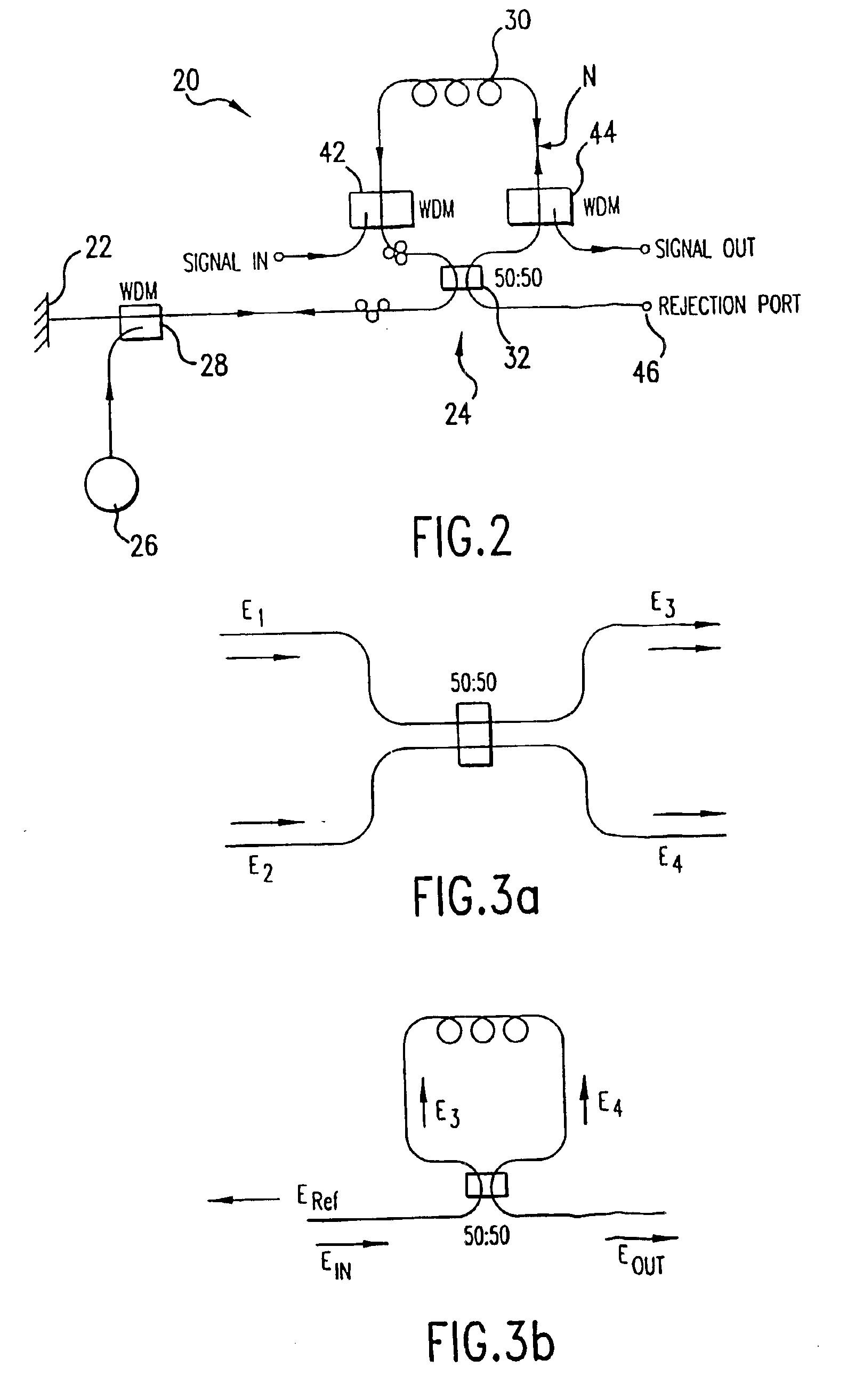
[0070]FIG. 2 illustrates the Sagnac Raman amplifier 20 that comprises at least two reflectors 22, 24 and a port 28 for coupling to a source of light. Specifically, reflector 22 may be any reflective structure such as a mirror. Reflector 24 is a loop reflector such as a Sagnac interferometer. In this embodiment, these two reflectors form there between an optical resonator. The light source 26 is a pumped fiber laser coupled through a WDM port 28 to the optical resonator. An optical signal is injected into the optical resonator and this signal is then amplified by the optical energy introduced by the light source 26. An optical signal input WDM port 42 is provided to allow the optical resonator to be used as an optical amplifier. The optical signal then exits from an optical signal output WDM port 44.

[0071]The light source 26 can be any suitable source of optical energy. Because the Raman effect relies upon intense optical energy, high power semiconductor or cladding-pumped fiber lase...

second embodiment

[0088]FIG. 4 shows the invention. A resonant cavity is formed between reflector 22 and reflector 24. Reflector 24 is a Sagnac interferometer including a dichroic coupler 32b and a fiber loop. Dichroic coupler 32b is used to provide frequency selectivity. The dichroic coupler provides nominally 50:50 coupling over the cascade Raman order wavelengths, but a ratio that is closer to 100:0 for the signal wavelength. Thus, for a 1.3 μm system the 50:50 coupling would be provided for wavelengths less than 1300 nm and the 100:0 coupling would be provided for wavelengths greater than 1300 nm. The advantage of this configuration is that it is easier to make a balanced Sagnac interferometer, and the fiber in the Sagnac interferometer may be packaged more simply. One possible disadvantage of this configuration is that the dichroic coupler may be more difficult or expensive to implement. The signal input WDM port 42b is positioned in the cavity at a location between the two reflectors 22 and 24 ...

third embodiment

[0089]FIG. 5 illustrates the invention in which reflector 22 of FIG. 2 has been replaced by a series of grating reflectors 50 and 52. The grating filters may be selected to provide 100 percent reflection at selected wavelengths, such as at 1175 nm and 1240 nm. The advantage of the configuration of FIG. 5 is that a narrow pump line width can be achieved. The disadvantage is that the configuration is more complicated and more expensive to fabricate.


PUM


Abstract

A nonlinear polarization amplifier stage includes a gain medium operable to receive a multiple wavelength optical signal. The amplifier further includes a pump assembly operable to generate a plurality of pump wavelengths forming a pump spectrum comprising a plurality of peaks. The amplifier also includes a coupler operable to introduce the at least one of the plurality of pump wavelengths to the gain medium to facilitate amplification of at least a portion of the multiple wavelength optical signal through nonlinear polarization. In one particular example, at least a wavelength or an intensity of the at least one of the plurality of pump wavelengths is manipulated to affect the shape of a gain curve associated with the multiple wavelength optical signal in the amplifier stage.

Description

CROSS-REFERENCE TO RELATED CASES[0001]This application is a continuation of U.S. patent application Ser. No. 10 / 033,848, filed Dec. 19, 2001, now abandoned, and entitled “BROADBAND SAGNAC RAMAN AMPLIFIERS AND CASCADE LASERS,” which is a divisional of U.S. patent application Ser. No. 9 / 550,730 filed Apr. 17, 2000, now U.S. Pat. No. 6,370,164.[0002]U.S. Pat. No. 6,370,164 is a divisional of U.S. patent application Ser. No. 09 / 110,696, filed Jul. 7, 1998, now, U.S. Pat. No. 6,052,393. U.S. Pat. No. 6,052,393 is a continuation-in-part of U.S. patent application Ser. No. 08 / 773,482 filed Dec. 23, 1996, now U.S. Pat. No. 5,778,014, which claims the benefit of U.S. provisional patent application Ser. No. 60 / 080,317 filed Apr. 1, 1998.TECHNICAL FIELD OF THE INVENTION[0003]The present invention relates generally to Sagnac Raman amplifiers and lasers for telecommunications, cable television (CATV), and other fiber-optics applications. More particularly, the invention relates to broadband Sagn...

Claims


Application Information

Patent Timeline
Patent Type & Authority Patents(United States)
IPC IPC(8): H01S3/30H01S3/094
CPCH01S3/302H01S3/094003
Inventor ISLAM, MOHAMMED N.
Owner XTERA COMM
Why Eureka
Try Eureka