Tunnel device level shift circuit

a technology of tunneling gate and shift circuit, which is applied in the field of floating gate circuit, can solve the problems of low accuracy of circuit b>70/b>, net negative charge on floating gate fg, and the consideration of dual conduction digital programming as less efficient and desirable ways, so as to improve accuracy and stability.

Inactive Publication Date: 2005-07-05
XICOR
View PDF11 Cites 23 Cited by
  • Summary
  • Abstract
  • Description
  • Claims
  • Application Information

AI Technical Summary

Benefits of technology

[0018]An advantage of the present invention is that it enables the generation of a reference voltage of improved accuracy and stability over prior art vo...

Problems solved by technology

This results in a net negative charge on floating gate fg.
Second, the accuracy of circuit 70 is also limited because the potential of floating gate fg changes another 100 mV to 200 mV over time after it is set due to various factors, including detrapping of the tunnel devices and dielectric relaxation of all the floating gate fg capacitors.
However, this method has only been used in digital circuits to program the floating gate to either a “1” condition or a “0” condition to provide memory storage.
The precise charge on the floating gate in such applications is not of concern and so is not precisely controlled in such circuits.
According to the prior art, such dual conduction digital programming of a f...

Method used


Image

  • Tunnel device level shift circuit
  • Tunnel device level shift circuit
  • Tunnel device level shift circuit

Examples


Embodiment Construction

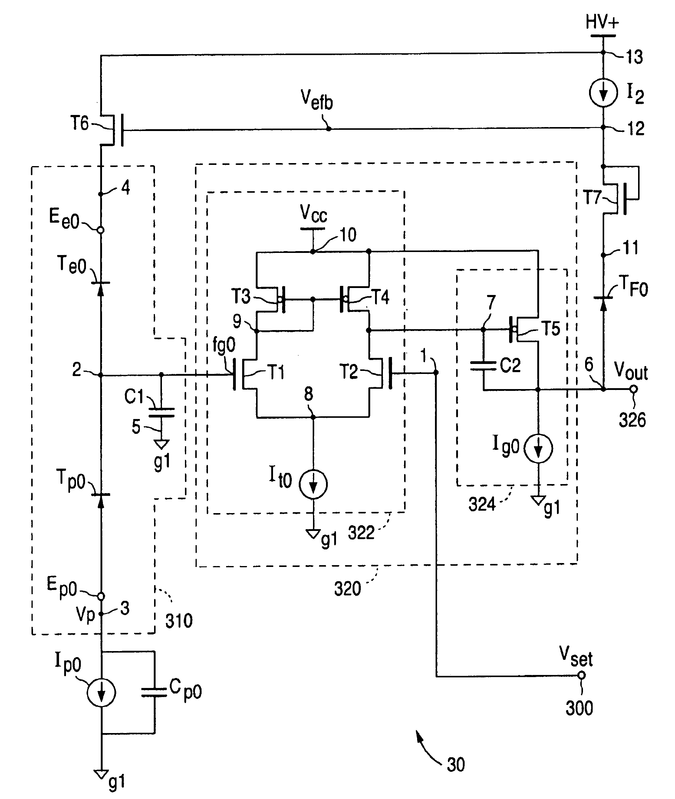
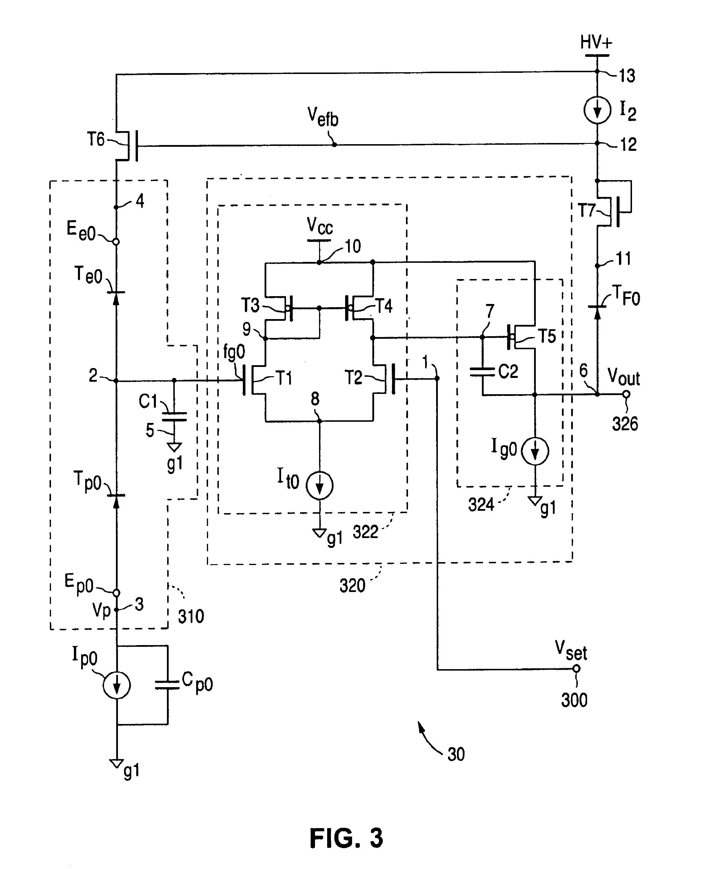
[0035]The present invention is a circuit for level shifting the output of a floating gate circuit to a voltage that enables tunnel devices coupled to a floating gate in the circuit to operate in dual conduction for setting the floating gate to a desired voltage. FIG. 3 is a circuit diagram of a differential single floating gate circuit 30 according to the present invention for accurately setting a floating gate to an analog voltage during a high voltage set mode or set cycle. FIG. 4A is a circuit diagram of a differential dual floating gate circuit 40 according to another embodiment of the present invention. Circuit 40 is also used to accurately set a floating gate to an analog voltage during a high voltage set mode. Once the analog voltage level is set, both circuit 30 and circuit 40 can then be configured during a read mode as a precise voltage comparator circuit with a built-in voltage reference or a precise voltage reference circuit. Circuit 30 and circuit 40 are preferably impl...


PUM


Abstract

A floating gate circuit has a level shift circuit. The floating gate circuit includes: a floating gate; a first and second tunnel device formed respectively between a first and second tunnel electrode; a first circuit coupled to the floating gate for generating an output voltage at an output terminal; a level shift circuit having a third tunnel device coupled between the output terminal and the first tunnel electrode; and a second circuit for causing a first current to flow through the first and second tunnel devices and for causing a second current to flow through the third tunnel device. The floating gate circuit then settles to a steady state condition during the set mode such that the first and second currents are approximately equal and the floating gate voltage and the output voltage are approximately equal.

Description

FIELD OF THE INVENTION[0001]This invention relates to a floating gate circuit, and more specifically to a level shift circuit used to level shift the output of the floating gate circuit to a voltage that enables tunnel devices coupled to a floating gate to operate in dual conduction to precisely set the floating gate to a desired voltage during a set mode.BACKGROUND OF THE INVENTION[0002]Programmable analog floating gate circuits have been used since the early 1980's in applications that only require moderate absolute voltage accuracy over time, e.g., an absolute voltage accuracy of 100-200 mV over time. Such devices are conventionally used to provide long-term non-volatile storage of charge on a floating gate. A floating gate is an island of conductive material that is electrically isolated from a substrate but capacitively coupled to the substrate or to other conductive layers. Typically, a floating gate forms the gate of an MOS transistor that is used to read the level of charge ...

Claims


Application Information

Patent Timeline
IPC IPC(8): G11C16/02G11C11/34G11C16/04G11C16/06G11C27/00H01L29/768H01L29/66G11C16/10G11C16/34H01L
CPCG11C16/10G11C16/3468G11C27/005G11C16/0441
Inventor OWEN, WILLIAM H.
Owner XICOR
Why Eureka
Try Eureka