
Six to ten KHz, or greater gas discharge laser system

a laser system and gas discharge technology, applied in the field of electric discharge gas lasers, can solve the problems of lnp performance becoming a serious challenge, contaminating the gas, and high downtime, and achieves improved and more powerful motors, reliable long-term operation, and improved gas flow rate

Inactive Publication Date: 2005-07-05
CYMER INC
View PDF56 Cites 32 Cited by
  • Summary
  • Abstract
  • Description
  • Claims
  • Application Information

AI Technical Summary

Benefits of technology

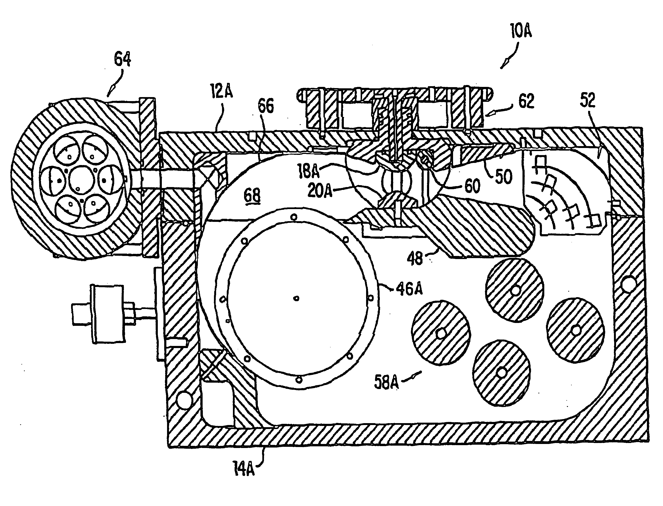
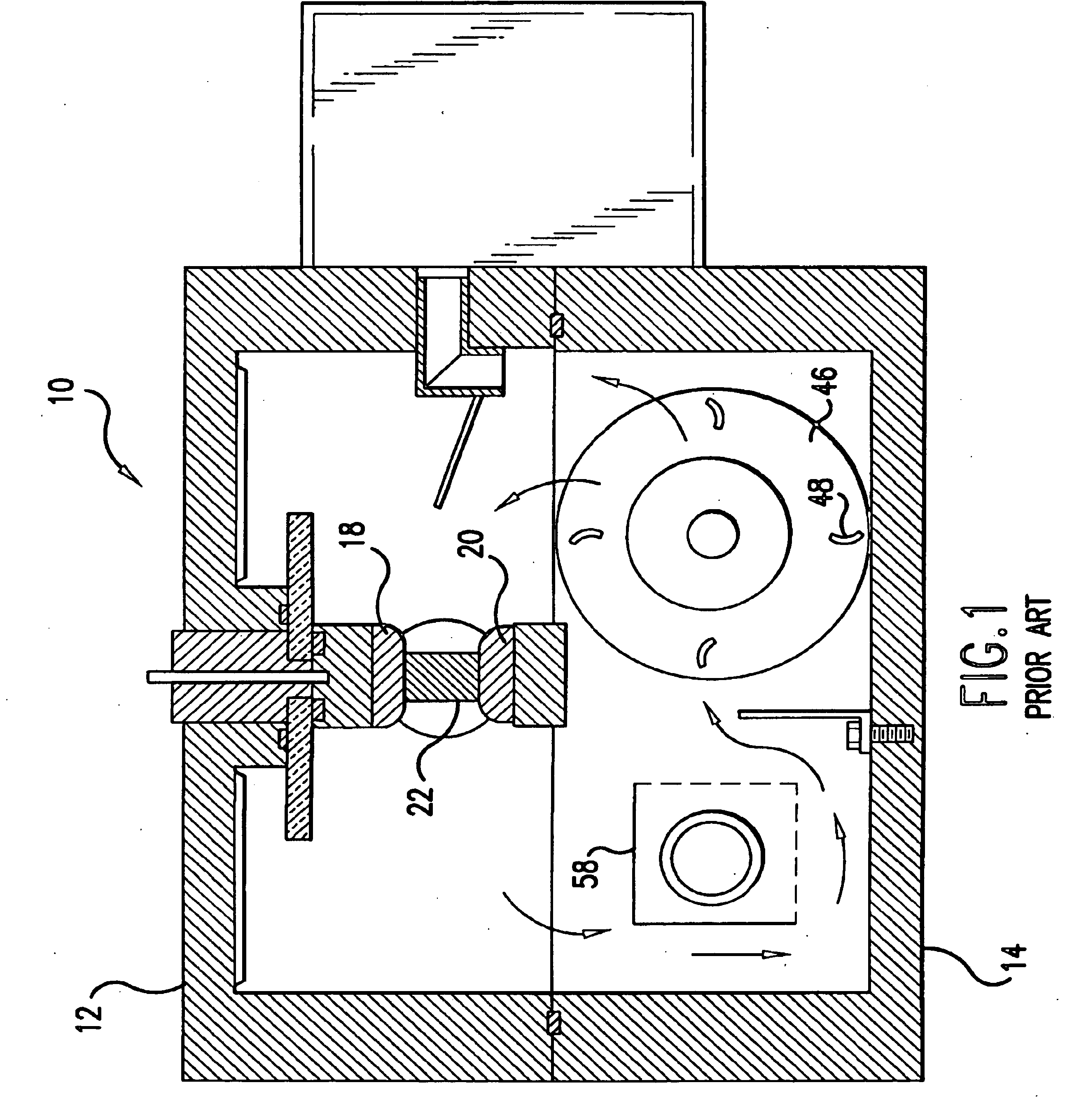
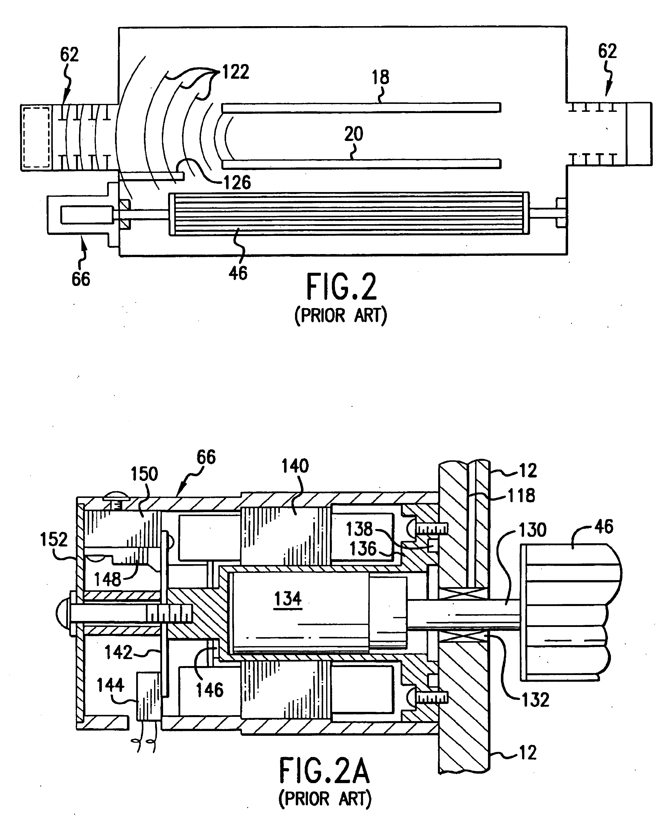
[0011]The present invention provides gas discharge laser systems capable of reliable long-term operation in a production line capacity at repetition rates in the range of 8,000 to 10,000 pulses power second or greater. Preferred embodiments are configured as KrF, ArF and F2 lasers used for light sources for integrated circuit lithography. Improvements include a modified high voltage power supply capable for charging an initial capacitor of a magnetic compression pulse power system to precise target voltages 6,000 to 10,000 times per second and a feedback control for monitoring pulse energy and determining the target voltages on a pulse-by-pulse basis. Several techniques are disclosed for removing discharge created debris from the discharge region between the laser electrodes during the intervals between discharges. In one embodiment the width of the discharge region is reduced from about 3 mm to about 1 mm so that a gas circulation system designed for 4,000 Hz operation could be utilized for 10,000 Hz operation. In other embodiments the gas flow between the electrodes is increased sufficiently to permit 10,000 Hz operation with a discharge region width of 3 mm. To provide these substantial increased gas flow rates, Applicants have disclosed preferred embodiments that utilize tangential fans of the prior art but with improved and more powerful motors and novel bearing designs. New bearing designs include both ceramic bearings and magnetic bearings. In other embodiments, some or all of the gas circulati

Problems solved by technology

Corrosion of the bearings and bearing lubrication can contaminate the gas.
These excimer lasers, when used for integrated circuit lithography, are typically operated on a fabrication line “around-the-clock”; therefore down time can be expensive.
As repetition rates increase maintaining stable performance by the LNP becomes a serious challenge.

Method used


Image

  • Six to ten KHz, or greater gas discharge laser system
  • Six to ten KHz, or greater gas discharge laser system
  • Six to ten KHz, or greater gas discharge laser system

Examples


second embodiment

[0160]a water cooled commutator utilizes as single cold plate assembly which is attached to the chassis base plate for the IGBT's and the diodes. The cold plate may be fabricated by brazing single piece nickel tubing to two aluminum “top” and “bottom” plates. As described above, the IGBT's and diodes are designed to transfer their heat into the cold plate by use of the previously mentioned ceramic disks underneath the assembly. In a preferred embodiment of this invention, the cold plate cooling method is also used to cool the IGBT and the diodes in the resonant charger. Thermally conductive rods or a heat pipe can also be used to transfer heat from the outside housing to the chassis plate.

Detailed Compression Head Description

[0161]The water-cooled compression head (see FIG. 5 for the components of the compression head) is similar in the electrical design to a prior art air-cooled version (the same type ceramic capacitors are used and similar material is used in the design saturable ...

first embodiment

[0245]This first embodiment of the present invention includes an ultra-pure N2 purge system which provides greatly improved performance and substantially increases component lifetime.

[0246]FIG. 19 is a block diagram showing important features of a first preferred embodiment the present invention. Five excimer laser components which are purged by nitrogen gas in this embodiment of the present system are LNP 2P, high voltage components 4P mounted on laser chamber 6P, high voltage cable 8P connecting the high voltage components 4P with upstream pulse power components 10P, output coupler 12P and wavemeter 14P. Each of the components 2P, 4P, 8P, 12P, and 14P are contained in sealed containers or chambers each having only two ports an N2 inlet port and an N2 outlet port. An N2 source 16P which typically is a large N2 tank (typically maintained at liquid nitrogen temperatures) at a integrated circuit fabrication plant but may be a relatively small bottle of N2. N2 source gas exits N2 sourc...


PUM


Abstract

The present invention provides gas discharge laser systems capable of reliable long-term operation in a production line capacity at repetition rates in the range of 6,000 to 10,0000 pulses power second. Preferred embodiments are configured as KrF, ArF and F2 lasers used for light sources for integrated circuit lithography. Improvements include a modified high voltage power supply capable for charging an initial capacitor of a magnetic compression pulse power system to precise target voltages 6,000 to 10,0000 times per second and a feedback control for monitoring pulse energy and determining the target voltages on a pulse-by-pulse basis. Several techniques are disclosed for removing discharge created debris from the discharge region between the laser electrodes during the intervals between discharges. In one embodiment the width of the discharge region is reduced from about 3 mm to about 1 mm so that a gas circulation system designed for 4,000 Hz operation could be utilized for 10,000 Hz operation. In other embodiments the gas flow between the electrodes is increased sufficiently to permit 10,000 Hz operation with a discharge region width of 3 mm. To provide these substantial increased gas flow rates, Applicants have disclosed preferred embodiments utilize tangential forms of the prior art but with improved and more powerful motors and novel bearing designs. New bearing designs include both ceramic bearings and magnetic bearings. In other embodiments, some or all of the gas circulation power is provided with a blower located outside the laser chamber. The outside blower can be located in the laser cabinet or in separate location.

Description

[0001]The present invention is a continuation-in-part of Ser. No. 10 / 141,216 filed May 7, 2002, now U.S. Pat. No. 6,693,939 Ser. No. 10 / 036,676 filed Dec. 21, 2001 now U.S. Pat. No. 6,882,674, Ser. No. 10 / 012,002, filed Nov. 30, 2001, now U.S. Pat. No. 6,625,191 Ser. No. 10 / 029,319, filed Oct. 17, 2001 now U.S. Pat. No. 6,765,946, Ser. No. 09 / 943,343, filed Aug. 29, 2001, now U.S. Pat. No. 6,567,450, Ser. No. 09 / 854,097, filed May 11, 2001, now U.S. Pat. No. 6,757,316, Ser. No. 09 / 794,782, filed Feb. 27, 2001, now U.S. Pat. No. 6,532,247, Ser. No. 09 / 768,753, filed Jan. 23, 2001, now U.S. Pat. No. 6,414,979, Ser. No. 09 / 684,629, and filed Oct. 6, 2000, now U.S. Pat. No. 6,442,181, Ser. No. 09 / 597,812, filed Jun. 19, 2000 now U.S. Pat. No. 6,529,531. This invention relates to gas discharge lasers and in particular to high repetition rate gas discharge lasers.BACKGROUND OF THE INVENTIONElectric Discharge Gas Lasers[0002]Electric discharge gas lasers are well known and have been availa...

Claims


Application Information

Patent Timeline
IPC IPC(8): G03F7/20H01S3/14H01S3/223H01S3/225H01S3/036H01S3/105H01S3/104H01S3/038H01S3/1055H01S3/13H01S3/134H01S3/131H01S3/11H01S3/097H01S3/04H01S3/137H01S3/22H01S3/08H01S3/139H01S3/00H01S3/041H01S3/0971H01S3/102H01S3/0975H01S3/23
CPCG03F7/70025G03F7/70333G03F7/70575G03F7/70933H01S3/036H01S3/038H01S3/0385H01S3/104H01S3/105H01S3/223H01S3/225G03F7/70041H01S3/2366H01S3/0057H01S3/0071H01S3/02H01S3/0387H01S3/0404H01S3/041H01S3/08009H01S3/08036H01S3/097H01S3/09702H01S3/0971H01S3/0975H01S3/1024H01S3/1055H01S3/1305H01S3/134H01S3/137H01S3/139H01S3/22H01S3/2207H01S3/2251H01S3/2256H01S3/2258H01S3/2333
Inventor WATSON, TOM A.UJAZDOWSKI, RICHARD C.IVASCHENKO, ALEX P.SANDSTROM, RICHARD L.SHANNON, ROBERT A.WEBB, R. KYLEPALENSCHAT, FREDERICK A.HOFMANN, THOMASRETTIG, CURTIS L.NESS, RICHARD M.MELCHER, PAUL C.ERSHOV, ALEXANDER I.
Owner CYMER INC
Learn More