
Temperature controlled window with a fluid supply system

Inactive Publication Date: 2005-07-12
APPLIED MATERIALS INC
View PDF38 Cites 162 Cited by
  • Summary
  • Abstract
  • Description
  • Claims
  • Application Information

AI Technical Summary

Benefits of technology

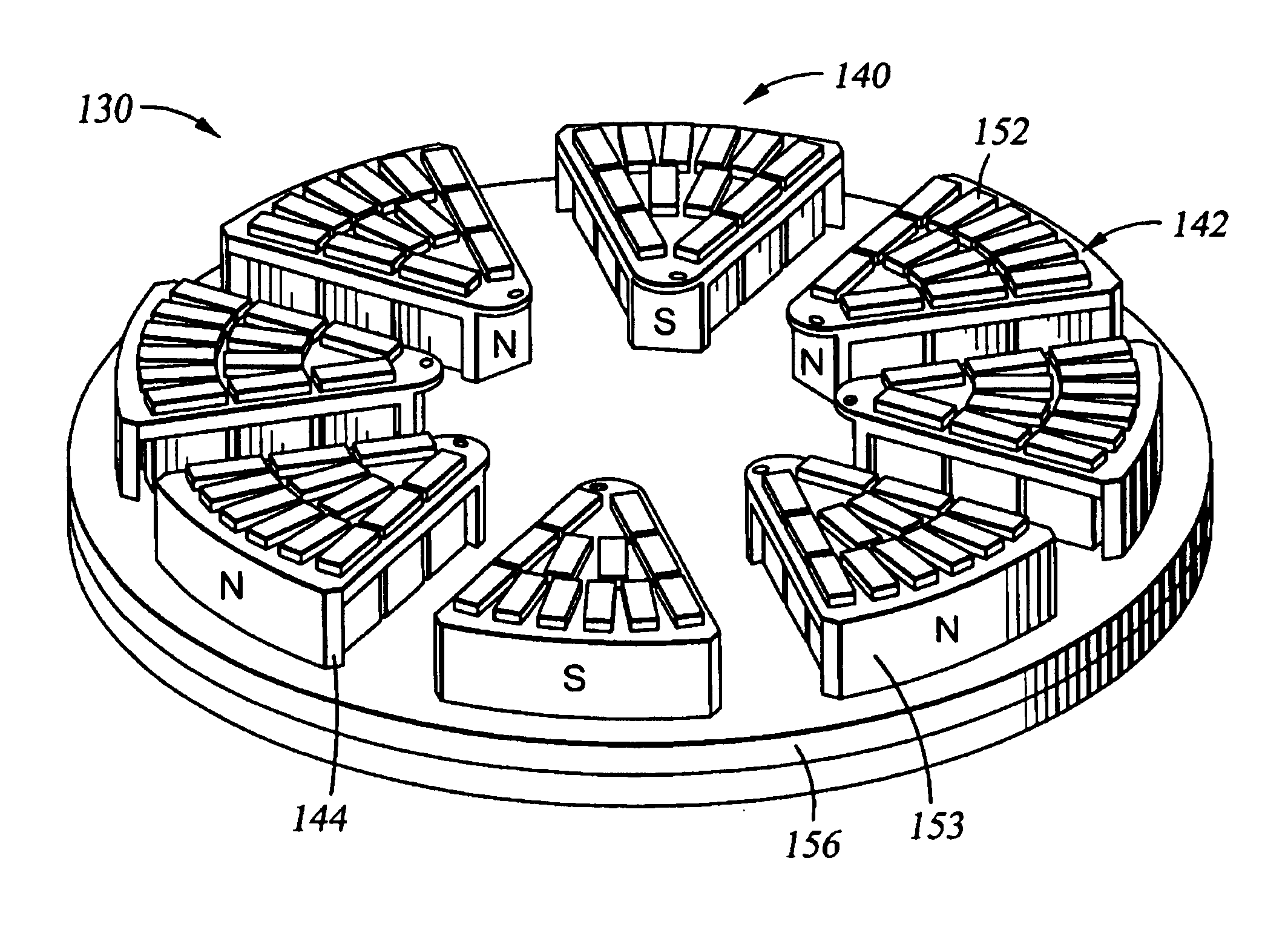
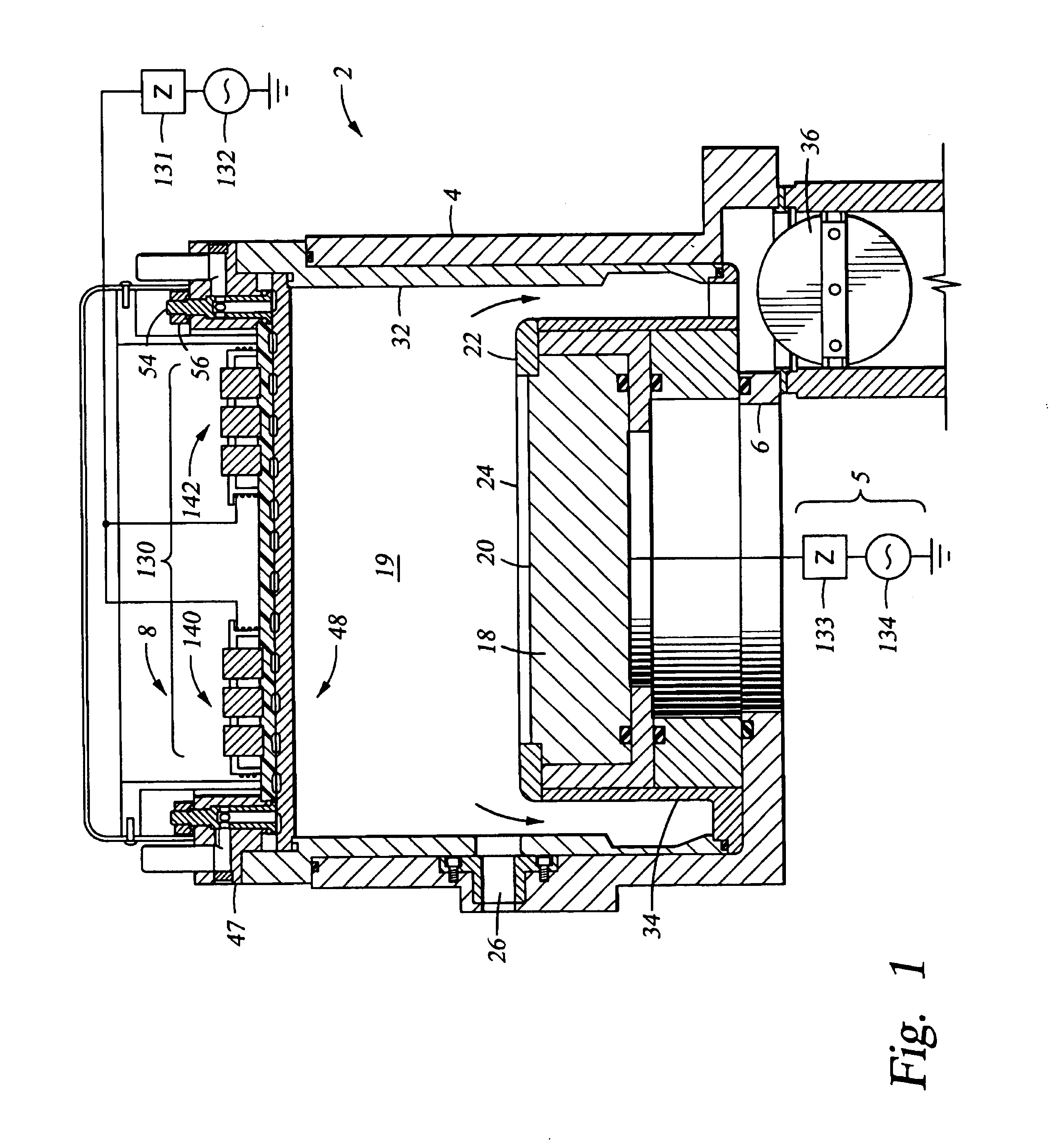
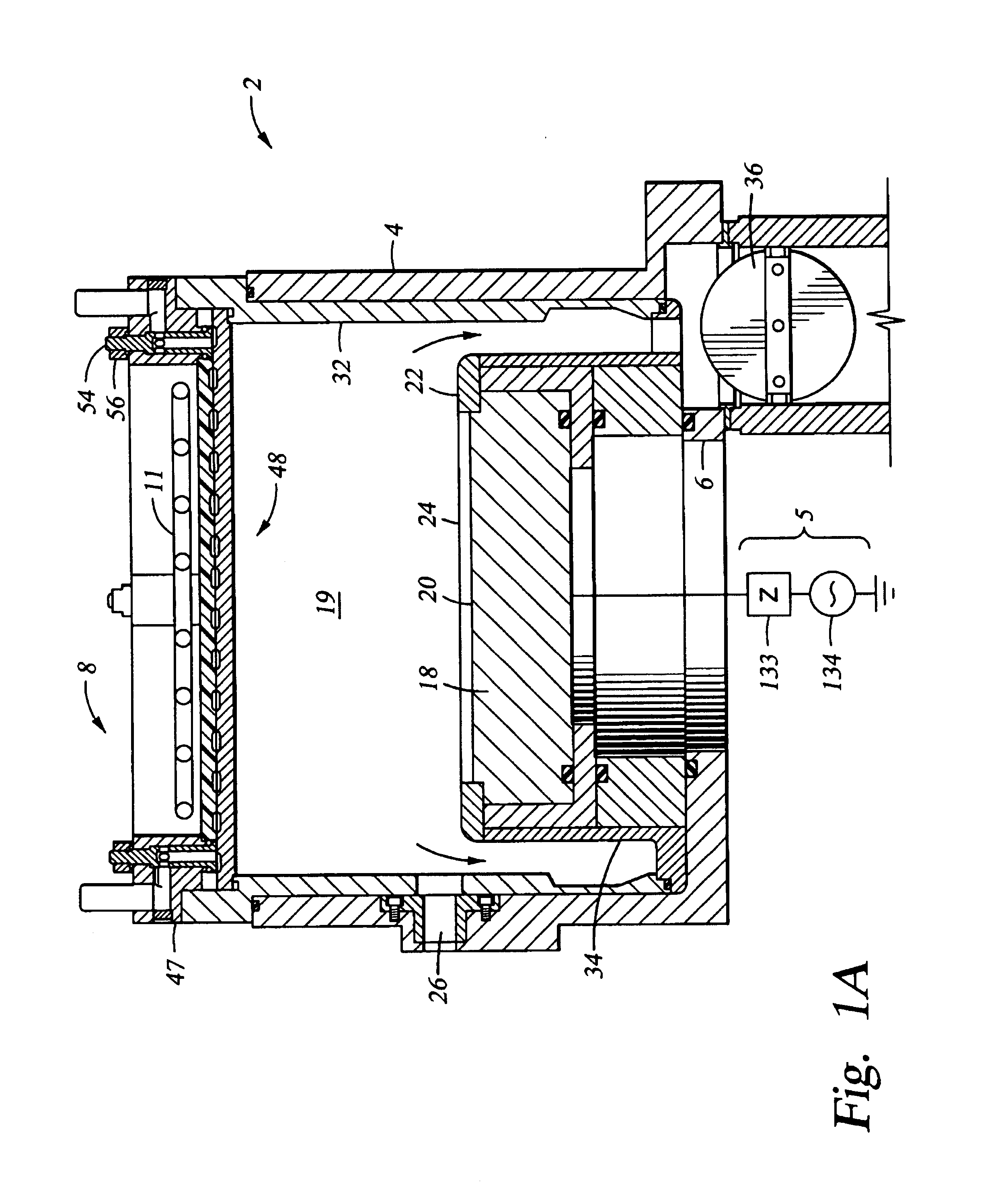
[0010]The present invention provides a method and apparatus for controlling the temperature of chamber components including ceramic, dielectric ceramic, and other non-metallic chamber components. One example of a temperature controlled chamber component of the invention includes a chamber lid acting as an energy transparent window or electrode (window / electrode) that allows efficient coupling of RF electromagnetic energy or microwave energy into the chamber. A fluid supply system delivers a fluid to a feedthrough and into a temperature control channel formed in the window or electrode. In one embodiment, a feedthrough mounts the chamber lid to a retaining ring and provides a conduit through which a fluid can be inlet and outlet from the temperature control channel.

Problems solved by technology

However, these attempts to achieve temperature control have failed to directly control the temperature of a dielectric, non-metallic or semiconductive window or electrode.
As a result, only indirect cooling has been achieved.
Moreover, such prior attempts have caused complications and interference when overhead coils or antennas have been called for in a plasma chamber.
Obviously, cooling apparatus compete for the same space or area as the coils or antenna or the cooling apparatus must be combined with the coils or antenna, limiting the optimization of either design.

Method used


Image

  • Temperature controlled window with a fluid supply system
  • Temperature controlled window with a fluid supply system
  • Temperature controlled window with a fluid supply system

Examples


Embodiment Construction

[0029]The present invention provides a temperature controlled chamber component, such as a ceramic, dielectric or semiconductive energy transparent window and / or electrode, particularly a chamber lid electrode for use in a substrate processing system. The invention also provides methods for controlling the temperature of chamber components, including the energy transparent window and / or electrode, and a substrate positioned in the chamber for processing. In one aspect, the invention provides a dielectric, ceramic or semiconductive window having an upper plate and a lower plate, which when bonded or otherwise secured together form an internal temperature control channel through which a cooling (or heating) fluid can be flowed to provide temperature control of the window. The invention will be described below initially with reference to embodiments having an energy transparent window. However, it should be understood that the description applies to chamber configurations which compris...


PUM

PropertyMeasurementUnit
Fractionaaaaaaaaaa
Fractionaaaaaaaaaa
Temperatureaaaaaaaaaa

Abstract

The present invention provides a temperature controlled energy transparent window or electrode used to advantage in a substrate processing system. The invention also provides methods associated with controlling lid temperature during processing and for controlling etching processes. In a preferred embodiment the invention provides a fluid supply system for the lid which allows the fluid to flow through a feedthrough and into and out of a channel formed in the window or electrode. The fluid supply system may also mount the window or electrode to a retaining ring which secures the window or electrode to the chamber. In another aspect the invention provides a bonded window or electrode having a first and second plate having a channel formed in the plates so that when the plates are bonded together they form a channel therein through which a temperature controlling fluid can be flowed. An external control system preferably regulates the temperature of the fluid.

Description

BACKGROUND OF THE INVENTION[0001]1. Field of the Invention[0002]The present invention relates to an apparatus and method for controlling the temperature of a surface in a processing chamber. More specifically, the invention relates to methods and apparatus for controlling the temperature of an energy transparent window or electrode of a processing chamber.[0003]2. Background of the Related Art[0004]Many processes for fabricating integrated circuits and other electronic devices, such as etching, chemical vapor deposition, and physical vapor deposition, are plasma-enhanced or plasma-assisted. These processes employ process gases which are excited to a plasma state within a vacuum chamber. As one example, plasma etching (typically referred to as “dry” etching) has become a well accepted process in semiconductor manufacturing. The etching process removes patterned material from the substrate surface located in a substrate processing system. Gases are the primary dry etch medium, and pla...

Claims


Application Information

Patent Timeline
IPC IPC(8): H01L21/00H01J37/32
CPCH01J37/321H01J37/32522H01L21/67069H01L21/67109
Inventor ROZENZON, YANLAVI, GILLEE, EVANS Y.CHOI, DONG HOHAMRAH, MATTLUSCHER, PAUL E.VAIDYA, KAUSHIKPU, BRYANFOVELL, RICHARD
Owner APPLIED MATERIALS INC
Learn More