
Point of sale (POS) terminal security system

a terminal and security technology, applied in the field of security systems, can solve problems such as the detection circuit of tampering, and achieve the effect of reducing the cost of manufacturing the terminal

Inactive Publication Date: 2005-07-12
HYPERCOM CORP
View PDF12 Cites 65 Cited by
  • Summary
  • Abstract
  • Description
  • Claims
  • Application Information

AI Technical Summary

Benefits of technology

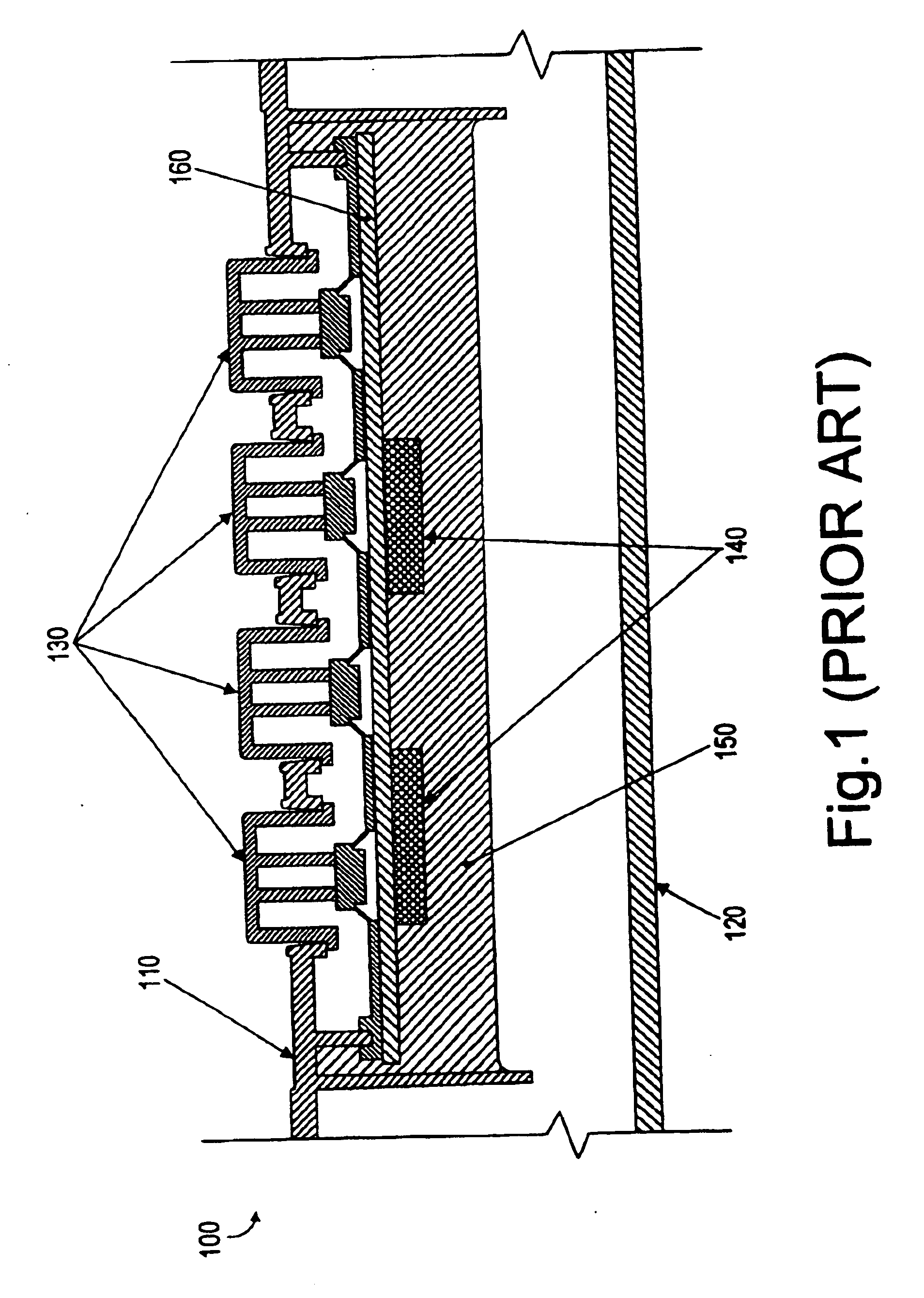
[0011]The system and method of the present invention provide a security system for electronic circuits (e.g. the electronic circuits within a secure POS terminal) that is both more tamper resistant and less expensive than the prior art epoxy potting. This is achieved by inserting an electrical connector between a first and a second circuit board contained within a case of the POS terminal. The first and the second circuit boards are any type of circuit board known in the art, including but not limited to, rigid circuit boards, flexible circuit boards, printed circuit boards, etc. If the case is opened the connectors no longer provide an electrical connection between the first and the second circuit boards, triggering a tamper detection circuit.
[0013]As a result, the secure POS terminal of the present invention overcomes the limitations of prior art potted terminals. By eliminating the potting process, in fact, the cost of manufacturing the terminal is reduced and there is no need for a special ventilation system. In addition, the circuitry within the terminal can be accessed for repair and maintenance purposes.

Problems solved by technology

If the case is opened the connectors no longer provide an electrical connection between the first and the second circuit boards, triggering a tamper detection circuit.

Method used


Image

  • Point of sale (POS) terminal security system
  • Point of sale (POS) terminal security system
  • Point of sale (POS) terminal security system

Examples


Embodiment Construction

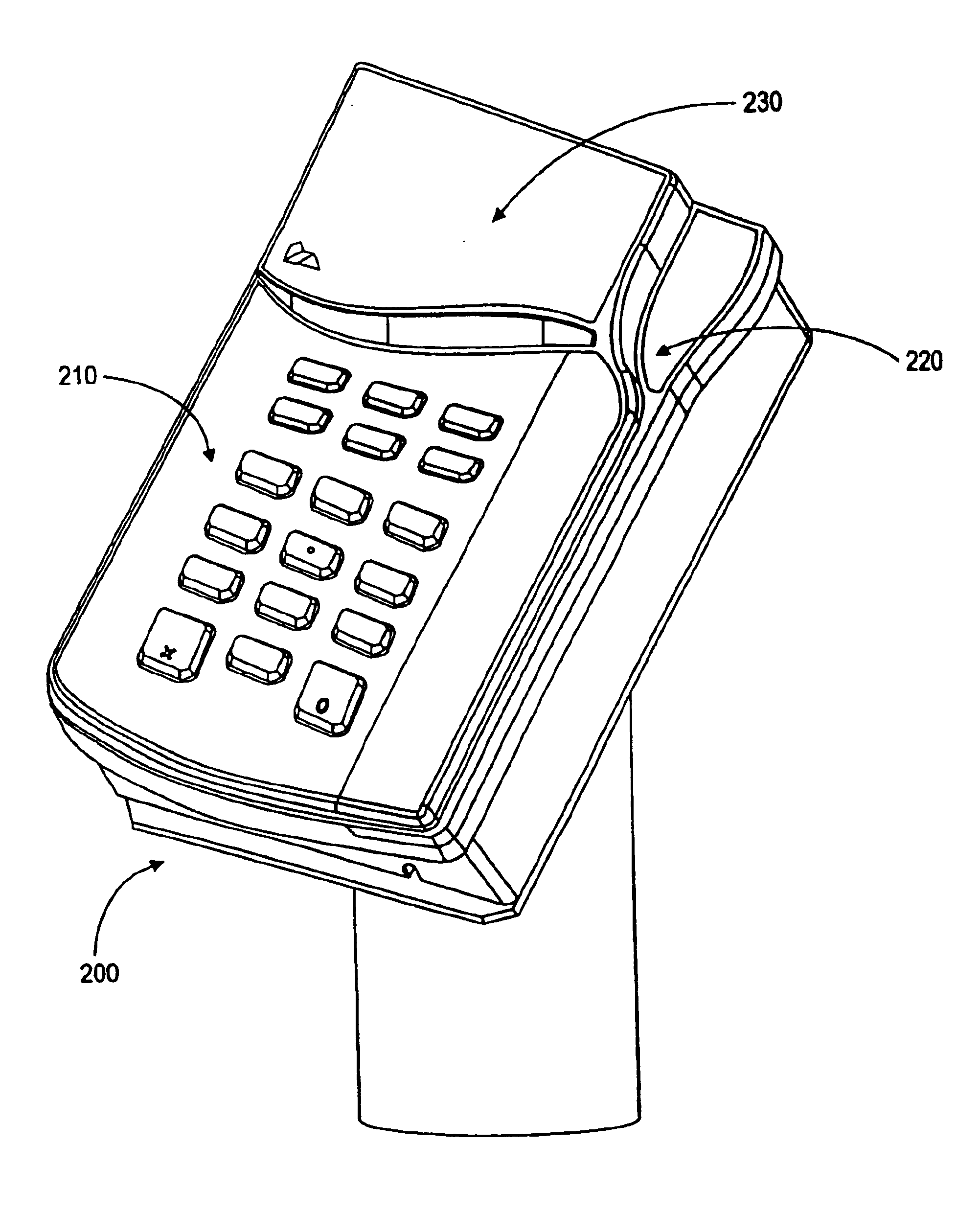
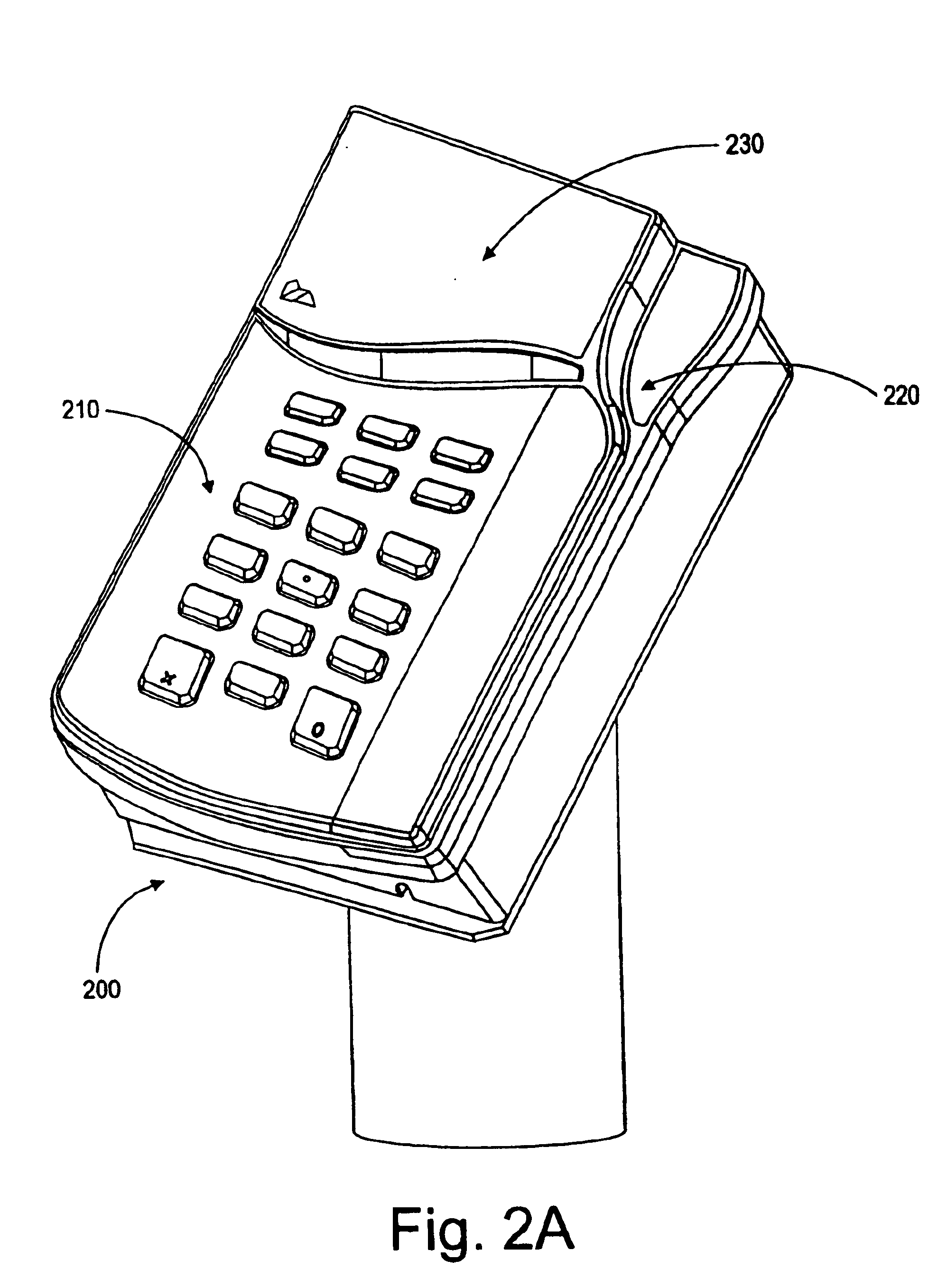
[0022]A secure POS terminal 200, in accordance with an embodiment of the invention, is shown in FIG. 2A. Secure POS terminal 200 includes a keypad 210, a card reader 220 and a display 230. To perform a payment transaction, a user of secure POS terminal 200 slides a card through card reader 220. The transaction details are then displayed to the user on display 230. The user can then enter additional information regarding the transaction, such as a security verification code or a PIN number via keypad 210. The information entered by the user is encrypted and transmitted through a secure communication channel to a bank or other transaction clearinghouse. Once the transaction is approved, the user is notified via display 230.

[0023]A cross-section of secure POS terminal 200 is shown in FIG. 2B. The circuitry that receives, stores and processes confidential information within POS terminal 200 is encased within security fence module 250. If security fence module 250 is penetrated, a securi...


PUM


Abstract

A security system for electronic circuits (e.g. electronic circuits contained within a secure POS terminal) is provided that is both more tamper resistant, and tamper responsive and less expensive than the prior art epoxy potting. This is achieved by inserting an electrical connector between a first and a second circuit board contained within a case of the POS terminal. The first and the second circuit boards are any type of circuit board known in the art, including both not limited to, rigid circuit boards, flexible circuit boards, printed circuit boards, etc. If the case is opened the connector no longer provides an electrical connection between the first and the second circuit boards, triggering a tamper detection circuit. In some embodiments of the invention, a flexible conductive film is wrapped around the circuit boards and the connector. If a tamperer attempts to penetrate the case of the POS terminal to disable the tamper detection circuit, the circuit on the flexible security film is interrupted, in turn triggering the tamper detection circuit. As a result, the secure POS terminal of the present invention overcomes the limitations of prior art potted terminals. By eliminating the potting process, in fact, the cost of manufacturing the terminal is reduced and there is no need for a special ventilation system. In addition, the circuitry within the terminal can be accessed for repair and maintenance purposes.

Description

CROSS REFERENCE TO RELATED APPLICATION(S)[0001]This application is a continuation of patent application having Ser. No. 09 / 586,678 filed Jun. 1, 2000 now U.S. Pat. No. 6,646,565, which is hereby fully incorporated herein by reference. Benefit of all earlier filing dates is claimed for all common subject matter.BACKGROUND OF THE INVENTION[0002]1. Field of the Invention[0003]The present invention relates generally to security systems and, more specifically, to security systems for electronic circuits.[0004]2. Related Art[0005]Point of sale (POS) terminals allow customers to make payments using a variety of payment instruments such as credit cards, debit cards, smart cards, ATM cards, etc. To ensure that the payment information transmitted from the POS terminals to a payment center is not intercepted, this information is typically encrypted and secured through other means (e.g., digital authentication) during transmissions.[0006]However, confidential payment information entered by the ...

Claims


Application Information

Patent Timeline
Patent Type & Authority Patents(United States)
IPC IPC(8): G06F1/00G06F21/00G07F7/10
CPCG06F21/86G06Q20/341G07F7/082G07F7/1008H05K1/0275H05K1/144G06F2221/2143H01H2239/032Y04S40/24H05K2201/10378H05K2201/2018Y04S40/20
Inventor FU, SHUZHENHANLEY, DAVID C.DEBRUIN, RAYMOND A.GRENFELL, JACK R.
Owner HYPERCOM CORP
Learn More