Vibratory cleaning mechanism for an antenna in a time-of-flight based level measurement system

a cleaning mechanism and level measurement technology, applied in the field of level measurement systems, can solve the problems of false measurement or signal loss, time-consuming, costly, and sometimes unsafe, and achieve the effect of improving the measurement signal

Active Publication Date: 2005-07-12
SIEMENS AG
View PDF15 Cites 27 Cited by
  • Summary
  • Abstract
  • Description
  • Claims
  • Application Information

AI Technical Summary

Benefits of technology

[0010]The vibratory cleaning mechanism provides a transducer coupled to the level measurement device in such a manner that, when excited, causes the radar antenna to vibrate. This vibration creates a cleaning action by causing solids or liquids adhered to the inner surface of the antenna to dislodge or fall off, improving the measurement signal.

Problems solved by technology

A build-up of material on the inside of a horn antenna prevents efficient signal transmission and also causes “noise” in received signals.
This build-up of material can cause false measurements or signal loss.
This is time consuming, costly, and sometimes unsafe.
While effective, this technique requires air or water to be supplied to the level measurement device which can be problematic in some applications.
Air and / or water supply is usually not available at the top of the container.
Thus, an air or water line must be installed which is costly to implement.
Typically, compressed air is used for purging because most solid applications cannot tolerate water inside the vessel.
Compressed air, however, is relatively costly to produce for continuous process requirements.

Method used


Image

  • Vibratory cleaning mechanism for an antenna in a time-of-flight based level measurement system
  • Vibratory cleaning mechanism for an antenna in a time-of-flight based level measurement system
  • Vibratory cleaning mechanism for an antenna in a time-of-flight based level measurement system

Examples


Embodiment Construction

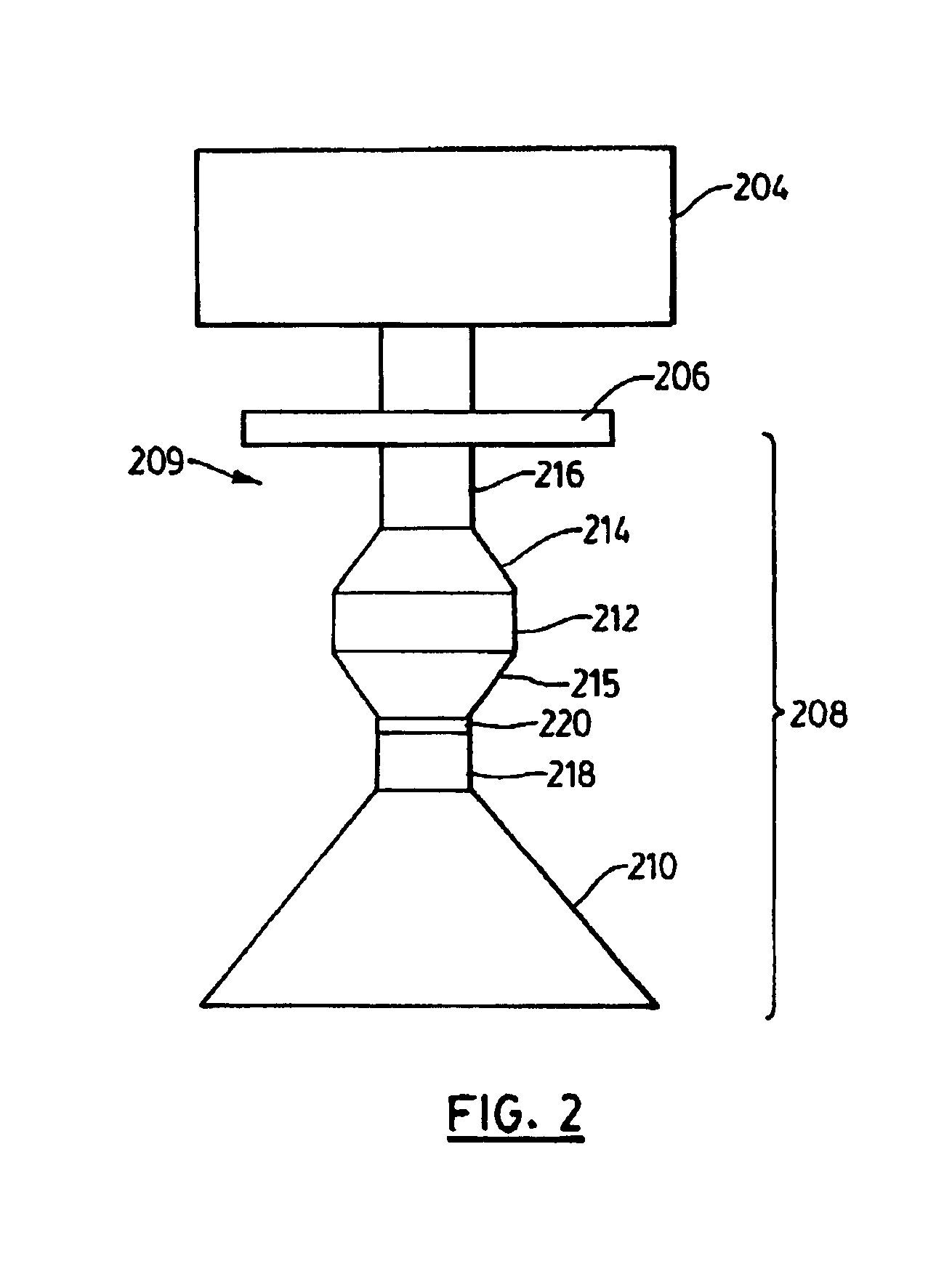
[0026]Reference is first made to FIG. 2 which shows in diagrammatic form a level measurement apparatus 200 with a radially mounted vibratory cleaning mechanism according to the present invention. The level measurement apparatus 200 comprises a level measuring device having a housing or enclosure 204 which contains electronic control circuitry such as shown in FIG. 11, and described more fully below, and an antenna assembly 208.

[0027]The level measurement apparatus 200 is mounted on top of a container or vessel (not shown) with the antenna assembly 208 extending into the interior of the container. The level measurement apparatus 200 is mounted to a flange (not shown) around an opening in the top of the container using bolts (not shown) or the like. The container contains a material, such as a liquid, solid or slurry, with a level determined by the top surface of the material. The top surface of the material provides a reflective surface or reflector for reflecting energy pulses emitt...


PUM


Abstract

An antenna assembly for use with a level measurement device for measuring the level of a material held in a container is provided. The antenna assembly includes an upper section for coupling to the level measurement device, and an antenna for transmitting energy pulses emitted by the level measurement device and receiving energy pulses reflected by the material in the container. A transducer module is disposed between the upper section and the antenna. A controller is operably connected to the transducer module, the transducer module being responsive to control signals of the controller for activating the transducer module such that the transducer module, when activated by the controller, vibrates the antenna to dislodge or remove material adhering to the antenna.

Description

FIELD OF THE INVENTION[0001]The present invention relates to level measurement systems, and more particularly to a vibratory cleaning mechanism for an antenna in a time-of-flight based level measurement system.BACKGROUND OF THE INVENTION[0002]Time-of-flight level measurement systems are used to determine the distance to a reflective surface (i.e. reflector) by measuring the time elapsed between the transmission of a signal towards a target and the return of the signal (i.e. echo) to the device. Time-of-flight level measurement systems may utilize ultrasonic pulses, pulse radar signals, or microwave energy signals.[0003]Pulse radar and microwave-based level measurement systems are typically preferred in applications where the atmosphere in the container or vessel is subject to large temperature changes, high humidity, dust and other types of conditions which can affect signal propagation. To provide a sufficient receive response, a high gain antenna is typically used. High gain usual...

Claims


Application Information

Patent Timeline
Patent Type & Authority Patents(United States)
IPC IPC(8): G01F23/284G01S13/00G01S13/08B08B7/02
CPCB08B7/02G01F23/284
Inventor TREGENZA, JAMES EDWARDLITTLE, TIMOTHY
Owner SIEMENS AG
Why Eureka
Try Eureka