
Shared mesh signaling algorithm and apparatus

a signaling algorithm and mesh technology, applied in the field of shared mesh signaling algorithm and apparatus, can solve the problems of two types of failures in the telecommunication network, the frequency of cable cuts is frequent and almost impossible to avoid, and the equipment failures resulting from man-made or natural disasters are additional possibilities

Inactive Publication Date: 2005-07-12
CIENA
View PDF8 Cites 62 Cited by
  • Summary
  • Abstract
  • Description
  • Claims
  • Application Information

AI Technical Summary

Benefits of technology

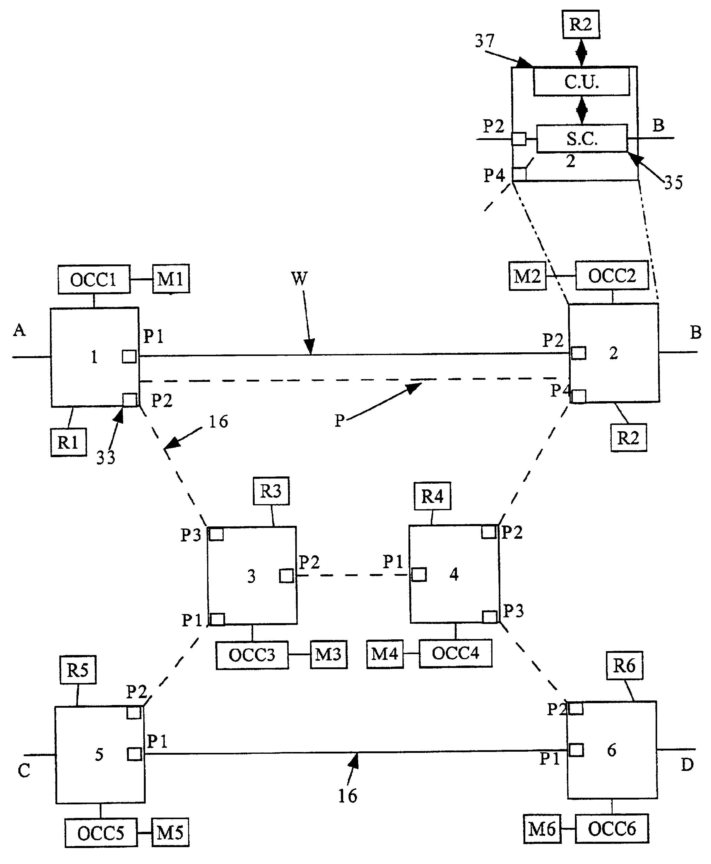
The present invention provides a shared mesh protection system for optical mesh networks that allows for the dynamic allocation of protection paths in case of network failure. The system includes a controller that monitors network traffic and defines a protection path based on the routing information of the network elements. The controller can detect network failures and quickly activate the protection path to prevent data loss. The system uses interrupt driven overhead bytes to communicate failure information between network elements and initiate the establishment of the protection path after a network failure has been detected. The technical effect of the invention is to provide a reliable and efficient protection path for optical mesh networks in case of network failure.

Problems solved by technology

The increased capacity of optical fibre has raised concerns about the reliability and survivability of an optical network, since a single cable cut or equivalent malfunction can impact a large amount of data traffic.
Cable cuts can be frequent and almost impossible to avoid, caused by human error or inclement weather.
Furthermore, equipment failures resulting from man made or natural disasters are additional possibilities.
Two types of failures can be experienced in a telecommunication network, such as line failures and module failures.
Accordingly, a line failure can include damage to the physical fibre and optical components, such as the malfunction of amplification equipment situated along the optical data path.
It should be noted that both line failures and module failures may disable the link between two nodes.
One disadvantage with BLSR systems is that they can not be easily applied to already existing (synchronous or asynchronous) communication systems without requiring costly equipment upgrades, for example a change in wavelength or bit rate involves a change in equipment.
In addition, BLSR systems have disadvantages in that they do not provide for 1:N protection (i.e. protection of N working channels using one protection channel) since path deployment is typically designated as 50% working and 50% protection, however as BLSR does not support Timeslot Interchange (TSI), the actual efficiency of the working bandwidth is about three quarters of the designated 50% deployment.
Furthermore, BLSR systems can have an additional limitation that all nodes around the ring must be of the same type and must have the same capacity.
However, one key problem with these well known mesh designs is the amount of time that is required to locate and establish the protection path and a subsequent new working path after a failure occurs.
The time it takes to re-establish communications after failure is critical since the time period during protection switching and protection path establishment should be small enough so as to unnoticable the devices or people using the data traffic.
These systems typically use the control layer of the network to assist in protection switching, which can provide undesirable protection switching times on the order of seconds.
This type of system could probably provide times in the 50 msec range, however would require protection bandwidth to be made available between every network element which would add to the complexity of the network architecture.
However, this method of using the signaling network has a disadvantage due to the processing of network overhead, whereby desirable protection times of less than 300 msec may not be achievable consistently.

Method used


Image

  • Shared mesh signaling algorithm and apparatus
  • Shared mesh signaling algorithm and apparatus
  • Shared mesh signaling algorithm and apparatus

Examples


Embodiment Construction

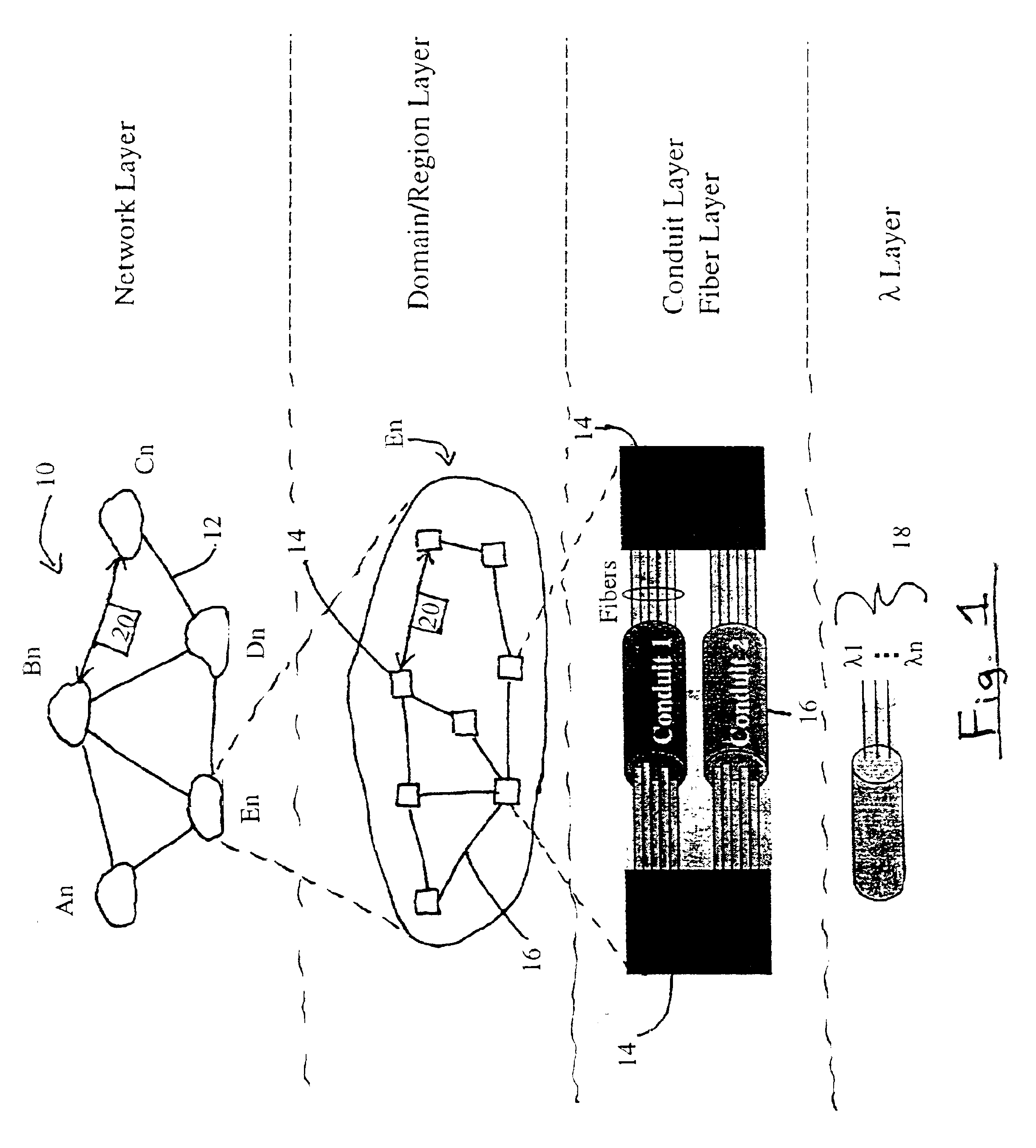
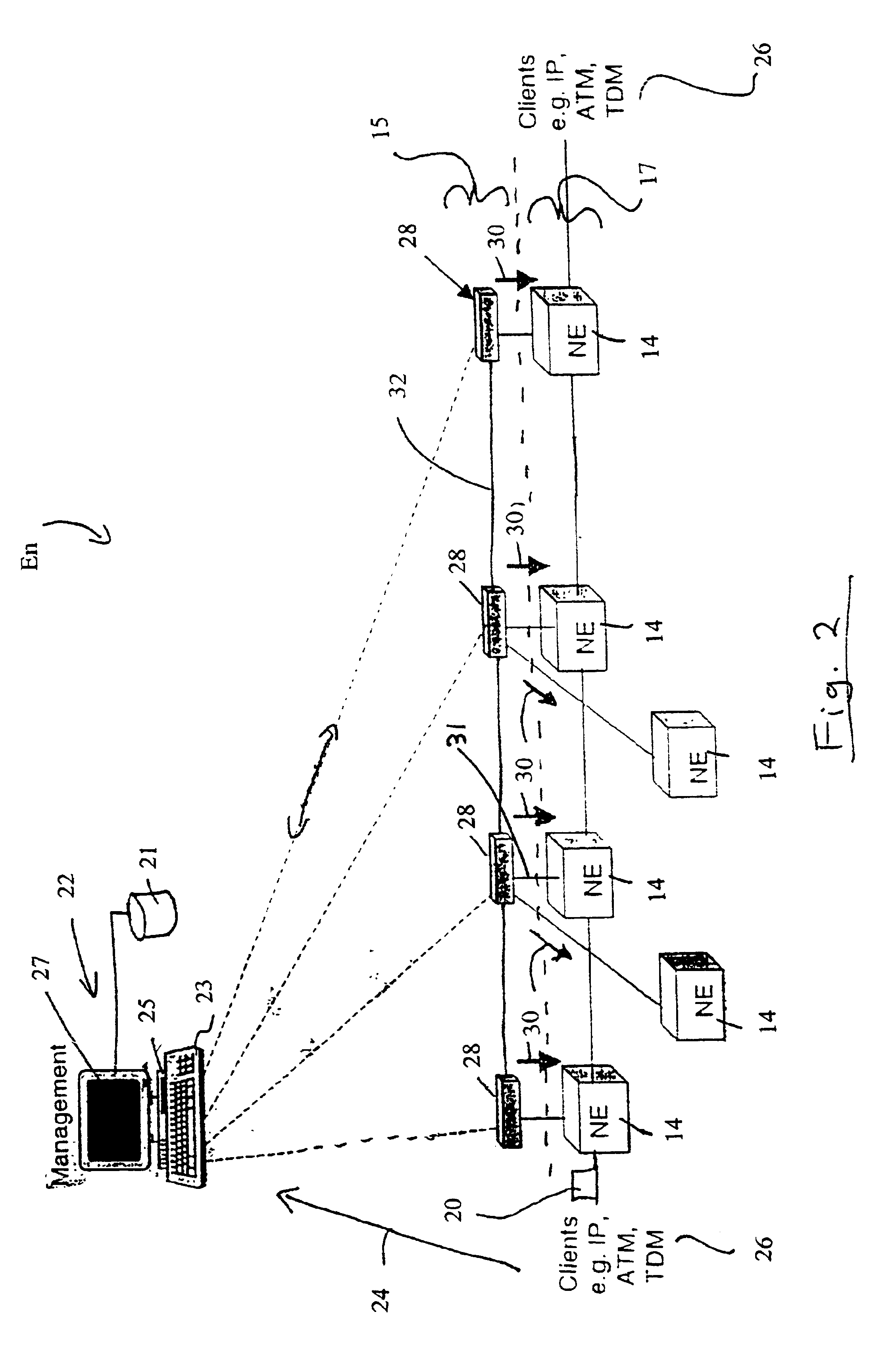
[0027]Referring to FIG. 1, a global telecommunication network 10 contains a series of sub-networks An, Bn, Cn, Dn, En interconnected by bulk data transmission mediums 12. These mediums 12 can consist of such as but not limited to optical fibre, wireless, and copper lines which are collectively referred to as the Backbone Network. Each sub-network An, Bn, Cn, Dn, En contains a plurality of network elements 14 interconnected by conduits 16, which can be collectively referred to as path layer 17 (see FIG. 2). These conduits 16 can consist of fibre optic cables, DSL (Digital Subscriber Loop), cable, and wireless mediums, wherein each conduit 16 can be capable of providing the transmission of multiple wavelengths 18 as required by the telecommunication network 10. The transmission structure of the telecommunication network 10 can be used by a variety of different carriers, such as ILECs, CLECs, ISPs, and other large enterprises to monitor and transmit a diverse mixture of data packets 20...


PUM


Abstract

A shared mesh protection scheme defines an associated protection path when a working connection is established. During the protection path definition, the corresponding protection path information is sent down to a switch card of network elements making up the protection path. Upon detection of the failure, the network elements using an overhead byte message will inform the routing source network element of the connection of the failure in the working path. The overhead bytes used are interrupt driven bytes located in the line and path overhead of network traffic. The routing source node of the connection will then send the corresponding overhead byte messages down the protection path to provide for protection path establishment according to the preloaded data located at the switch card. It should be noted that each connection can have a source and termination element which relates to the source from where the corresponding connection was set-up rather than the direction of the payload transmission. Therefore, once the failure has occurred the source elements will send messages using overhead bytes to the corresponding network elements along the protection path. Accordingly, routing tables located at the switch card of the network elements, set-up when the working path connections were initially established, determine this dynamically allocated protection path environment.

Description

[0001]The present invention relates to optical communication systems and, in particular, to apparatus and methods for providing protection signaling between network elements.BACKGROUND OF THE INVENTION[0002]Optical communication systems have become widely implemented in todays telecommunication networks. The Synchronous Optical Network (SONET) is a standard for Synchronous Telecommunication Signals used for optical transmission based on the synchronous digital hierarchy (SDH). SONET can provide the ability to combine and consolidate traffic through grooming, and can reduce the amount of back to back multiplexing in providing transport services for ATM, SMDS, and Frame Relay, etc. Furthermore, network providers can use SONET network features to reduce the operation costs of the transmission network.[0003]The network standards are ANSI T1.105 for SDH and Bellcore GR-253-CORE for SONET, which define the physical interface and optical line rate known as the optical carrier (OC) signals,...

Claims


Application Information

Patent Timeline
Patent Type & Authority Patents(United States)
IPC IPC(8): H04J3/08H04Q11/04
CPCH04J3/085H04J2203/0053H04J2203/006
Inventor DE BOERSHIELDS, JAMES A.TRUDEL, RICHARD
Owner CIENA
Learn More