
Method and system for power line network fault detection and quality monitoring

a technology of quality monitoring and power equipment, applied in the field of data communication, can solve the problems of affecting the quality of power equipment, and causing the creation of substantially instantaneous faults,

Active Publication Date: 2005-07-12
ENIKIA
View PDF6 Cites 157 Cited by
  • Summary
  • Abstract
  • Description
  • Claims
  • Application Information

AI Technical Summary

Benefits of technology

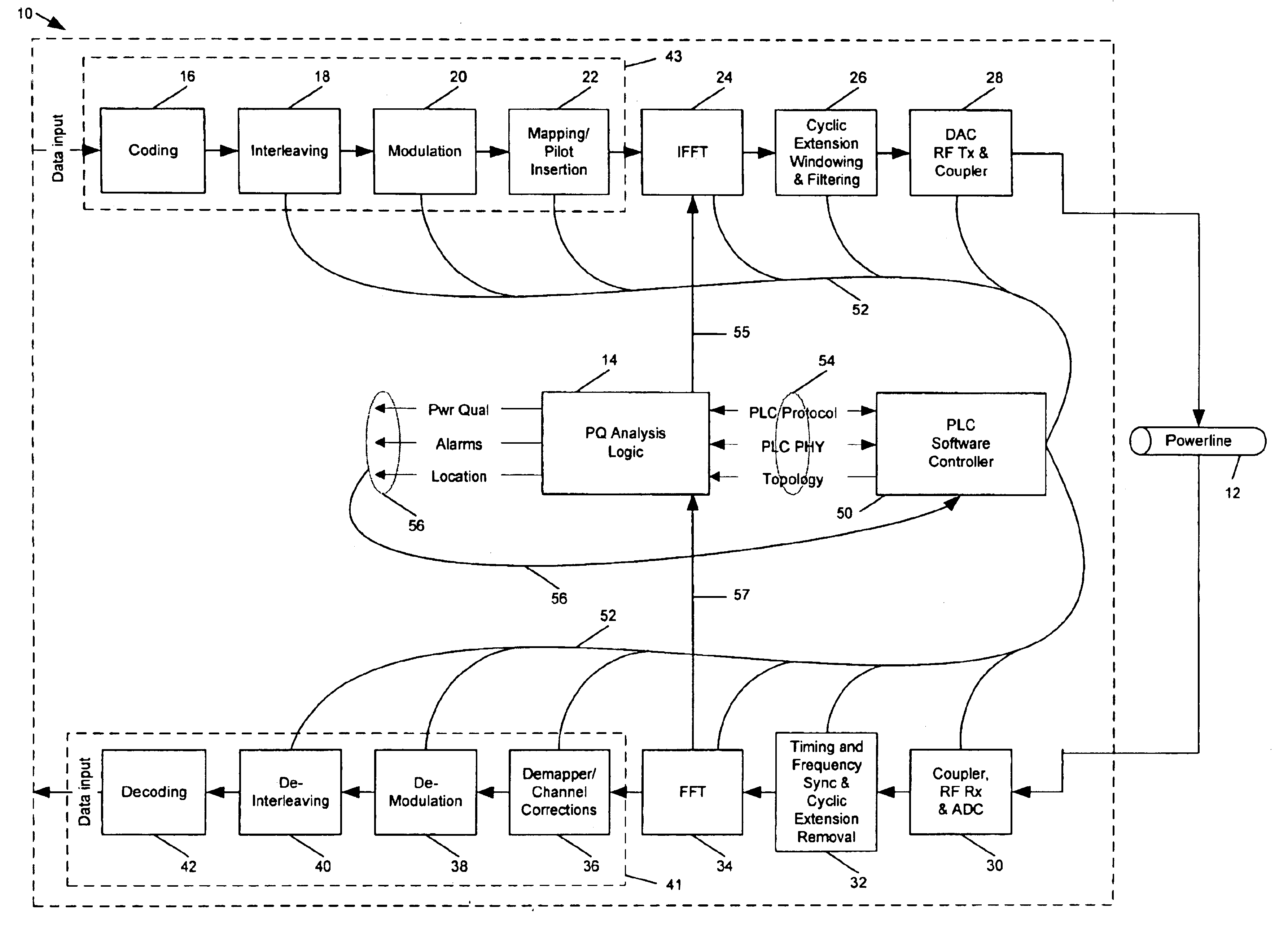
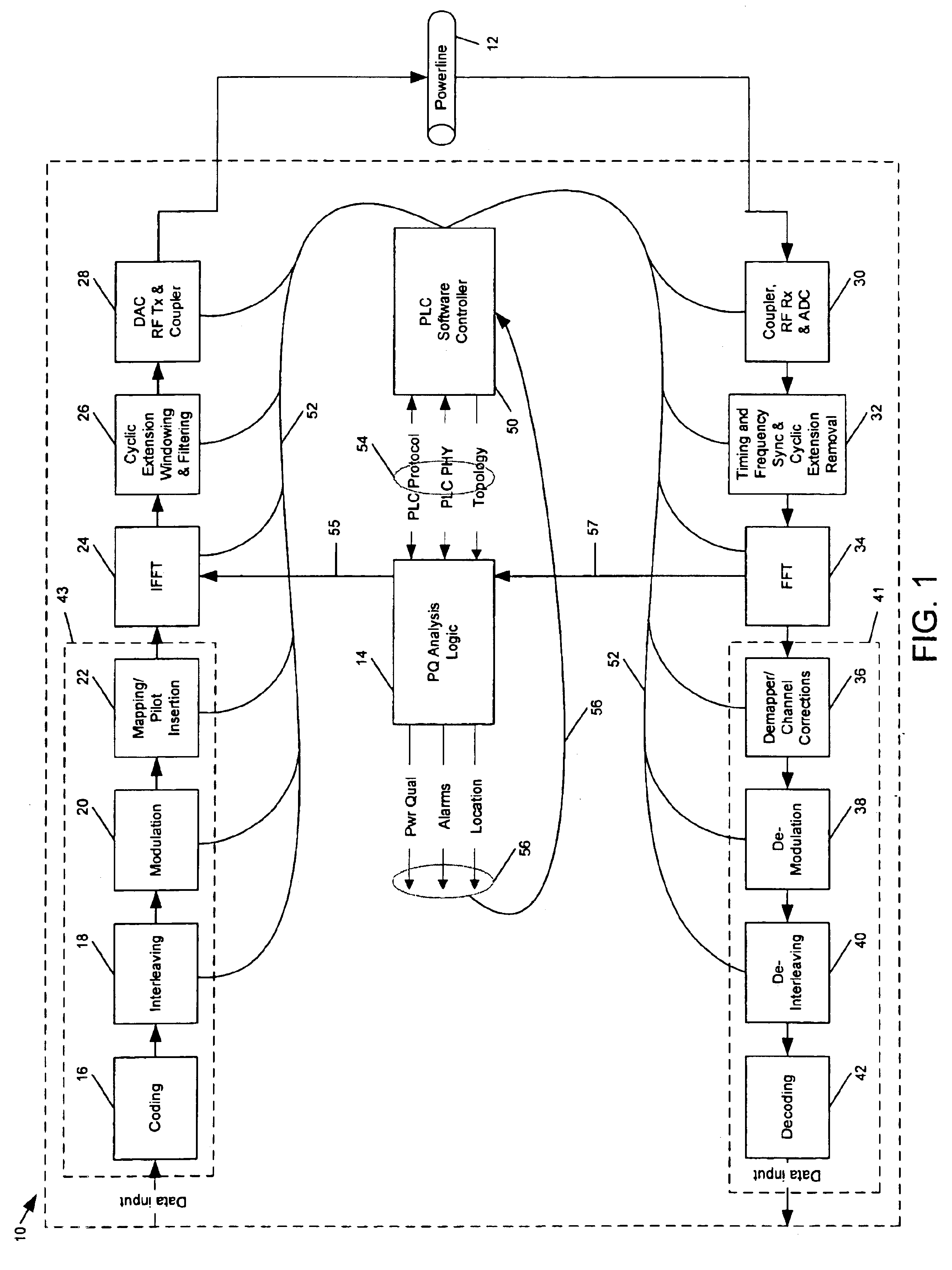
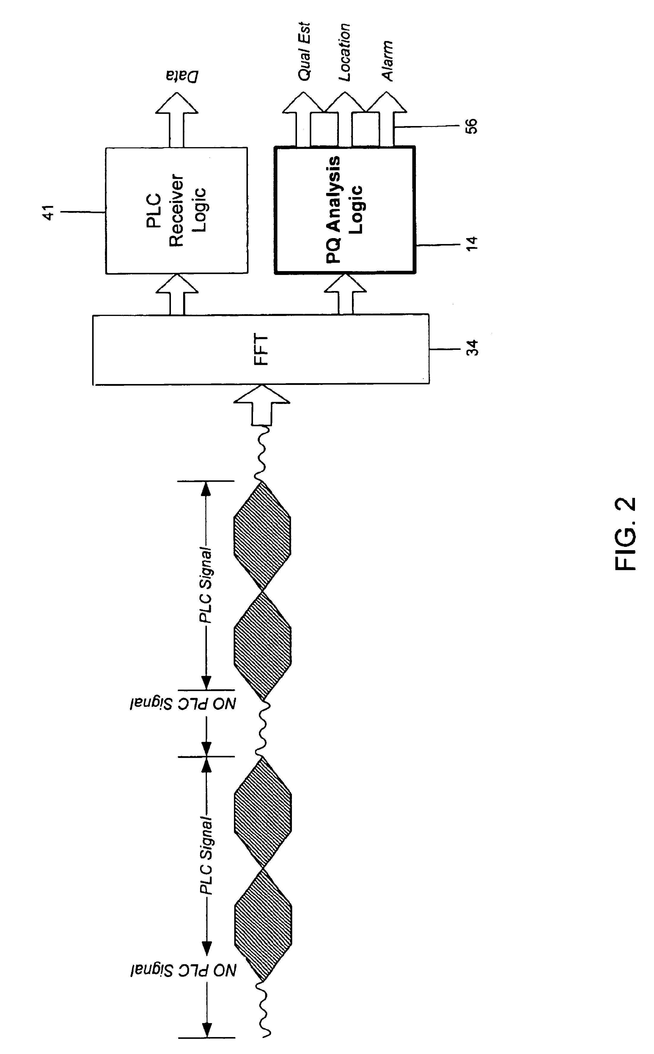
[0010]In a preferred embodiment, power quality analysis logic (“PQAL”) is included with or coupled to the PLC equipment and performs a power quality evaluation by processing the collected PLC silent data or a composite signal data with the extracted background noise to determine the presence of harmonics and power factor distortions. The processing performed by the PQAL includes analyzing the signal data associated with PLC silent intervals or signal (active) intervals whose noise signatures have been extracted with reference to fault signature data representative of power line network fault conditions and expected signal response and signal transfer function associated with the topology of the network. The PQAL, based on the fault evaluation, generates a fault alarm or a warning when an existing or anticipated fault is detected. In an exemplary preferred embodiment for detecting an anticipated fault, an anticipated fault is identified upon detection of the higher frequency harmonics that would be injected onto the power line network when insulation breakdown occurs at a failing transformer. In addition, the PQAL performs further fault evaluation processing to generate fault location data, which identifies the location of the element in the network creating an electric signal discontinuity condition that corresponds to an existing or anticipated fault. In a preferred embodiment, evaluation of historical records containing frequency and time domain response signatures, transfer function parameters, network impedance, and noise signatures helps to determine nature and location of an anticipated or existing fault. In a further embodiment, the PQAL, based on the fault evaluation, generates a power quality estimate that is representative of the power transmission quality of the network.

Problems solved by technology

When a power network element experiences a predetermined failure level, a fault is created in a power line network at the element that prevents satisfactory transmission of electric power downstream of the location of the fault, thereby cutting off the supply of electric power to downstream power users.
Power equipment components can fail either gradually or substantially instantaneously to create a fault in a power line network.
A substantially instantaneous fault can be created, for example, upon the complete severing of a connection between a transmission wire and another transmission wire or power wire connector, such as may occur when a utility pole to which a transmission wire is connected falls in a storm.
A power company, however, does not usually become aware of a gradual equipment failure, which may eventually become a fault, until the failure becomes so severe that a fault actually occurs.
Consequently, the power company does not have the necessary information to perform preventive maintenance on the failing element before the fault occurs.
For example, a power transformer, which is known to degrade gradually over time, may begin to operate at less than an optimal level, yet still operate at a level that permits a satisfactory, uninterrupted supply of electric power to downstream power users.
Thus, the power company is not aware of an existing or worsening equipment failure and the potential that the equipment failure can eventually become a fault.
Ultimately, an insulation failure in the transformer equipment may develop into a major failure event or fault in the power network.
The power company, however, typically learns that the transformer equipment has reached the end of its useful life only after a fault in the network is created.

Method used


Image

  • Method and system for power line network fault detection and quality monitoring
  • Method and system for power line network fault detection and quality monitoring
  • Method and system for power line network fault detection and quality monitoring

Examples


Embodiment Construction

[0022]The use of electrical signals traveling on a power line communications (“PLC”) network to perform power line network fault evaluation and quality monitoring is illustrated below in connection with a conventional, prior art PLC transceiver which further includes power quality analysis logic (“PQAL”) in accordance with the present invention. The addition of the PQAL to the conventional PLC transceiver is substantially a software modification requiring relatively few hardware changes and readily permits collection of data representative of power line signals on the network, during both PLC active and PLC silent intervals, for use in a power line network fault evaluation. The conventional PLC transceiver provides for a physical and electronic signal connection to the power line network, which includes the functionalities of generating and injecting wideband signals onto the power line network and receiving and processing power line signals. For the purpose of explaining the prefer...


PUM


Abstract

Fault detection and power network quality monitoring are performed for a power line network using power line communications (“PLC”) signal transceiving and data processing capabilities. Power line signals are continuously received and processed to obtain signal data representative of power line network operating conditions that are expressed in the received power line signals. The harmonic content and noise signature of the signal data are evaluated with reference to known fault signature data and power line network topology properties for detecting and identifying the location of an existing or anticipated fault in the power line network and assessing power transmission quality of the network.

Description

CROSS REFERENCE TO RELATED APPLICATION[0001]This application claims the benefit of U.S. Provisional Application No. 60 / 380,142 filed May 6, 2002, which is incorporated by reference herein.FIELD OF THE INVENTION[0002]This invention relates to the field of data communications over conventional utility electric power conveying media, and more particularly to using power line communications (“PLC”) equipment to detect and identify the location of an existing or anticipated fault in an electric power distribution network and to monitor the quality of the power network.BACKGROUND OF THE INVENTION[0003]A conventional utility electric power generating facility supplies electric power to electric power users over a vast and expansive electric power distribution grid containing many interconnected electric power line networks. The power line networks, which can be of various sizes, convey low, medium or high voltage electric power. Each of the networks includes such power transmission equipme...

Claims


Application Information

Patent Timeline
IPC IPC(8): H04B3/54G01R31/08G01R31/11
CPCH04B3/54G01R31/088G01R31/11H04B2203/5416H04B2203/5425H04B2203/5441H04B2203/5458H04B2203/5483H04B2203/5491H04B2203/5495H02J13/0024Y04S10/30Y04S40/146Y02E60/74Y02E60/7892Y04S40/122Y02E60/7823H02J13/00009H02J13/00002Y02E60/00Y04S40/121
Inventor LOGVINOV, OLEGDURFEE, LAWRENCE F.WALVIS, DIRK
Owner ENIKIA
Learn More