Method for fabricating surface mountable chip inductor

a technology of inductor and surface mounting, which is applied in the direction of resistive material coating, magnets, magnetic bodies, etc., can solve the problems of limited inductance, difficult surface mounting of conventional cylindrical inductor, and deterioration of electromagnetic interference conditions, and achieve good electric characteristics

Inactive Publication Date: 2005-07-19
CERATECH
View PDF12 Cites 9 Cited by
  • Summary
  • Abstract
  • Description
  • Claims
  • Application Information

AI Technical Summary

Benefits of technology

[0009]Accordingly, it is an object of the present invention to provide a surface mountable chip inductor having a good electric characteristic.

Problems solved by technology

In the meantime, as a result of the development of digital communication, the frequency being used is gradually extended to a high frequency region, and accordingly, electromagnetic interference conditions have deteriorated.
However, because the surface-mounted devices have a square shape, the conventional cylindrical inductor has difficulty in surface mounting.
On the contrary, because the number of stacked green sheet is limited, there is a limitation on inductance, and particularly because a width of internal electrode is limited, there is a limitation in permitting sufficient current.
Accordingly, it is inappropriate to use the stacked type inductor for power device, so its use is mainly limited for a low voltage and a low current.
In addition, the fabrication process itself is very intricate and lots of equipment costs are required.
In order to solve above-mentioned problems, an inductor fabricated by forming a metal layer on a cylindrical body and forming a coil pattern on the metal layer by trimming of the metal layer has been presented, however surface mounting of the fabricated inductor is difficult because of its cylindrical shape.
On the contrary, a square-shaped inductor is advantageous to surface mounting however a square-shaped inductor requires much time for trimming a metal layer on its surface using a laser, which causes fabrication costs to increase.

Method used


Image

  • Method for fabricating surface mountable chip inductor
  • Method for fabricating surface mountable chip inductor
  • Method for fabricating surface mountable chip inductor

Examples


Embodiment Construction

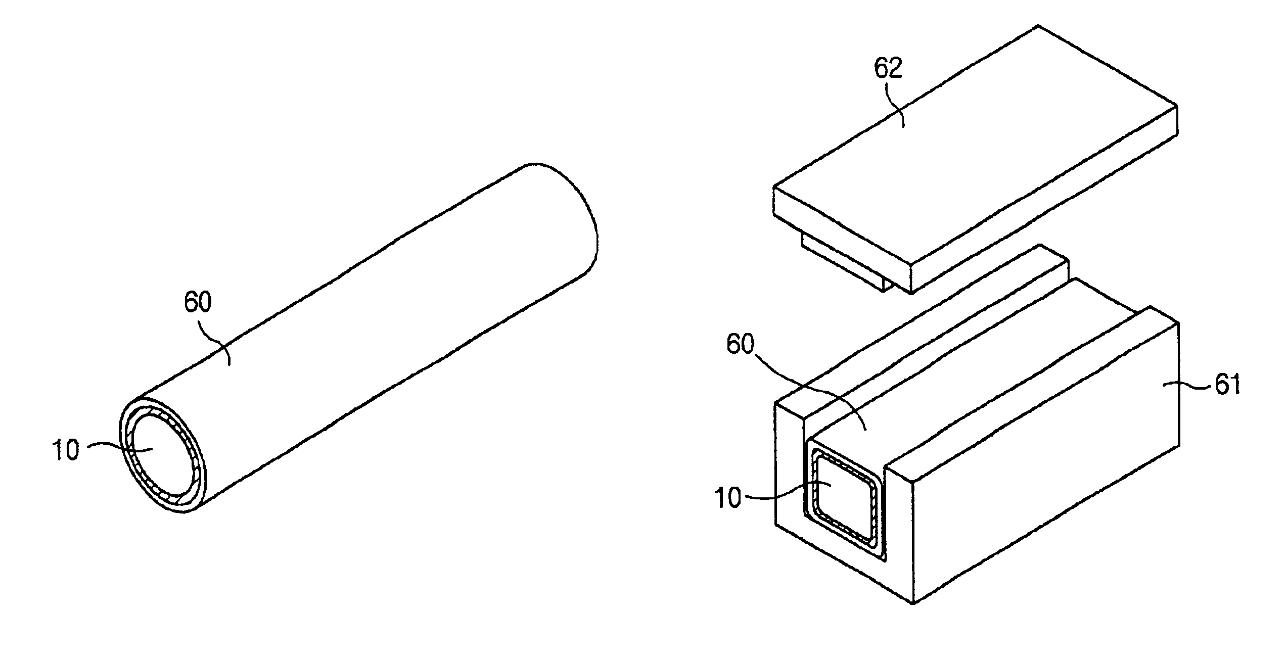
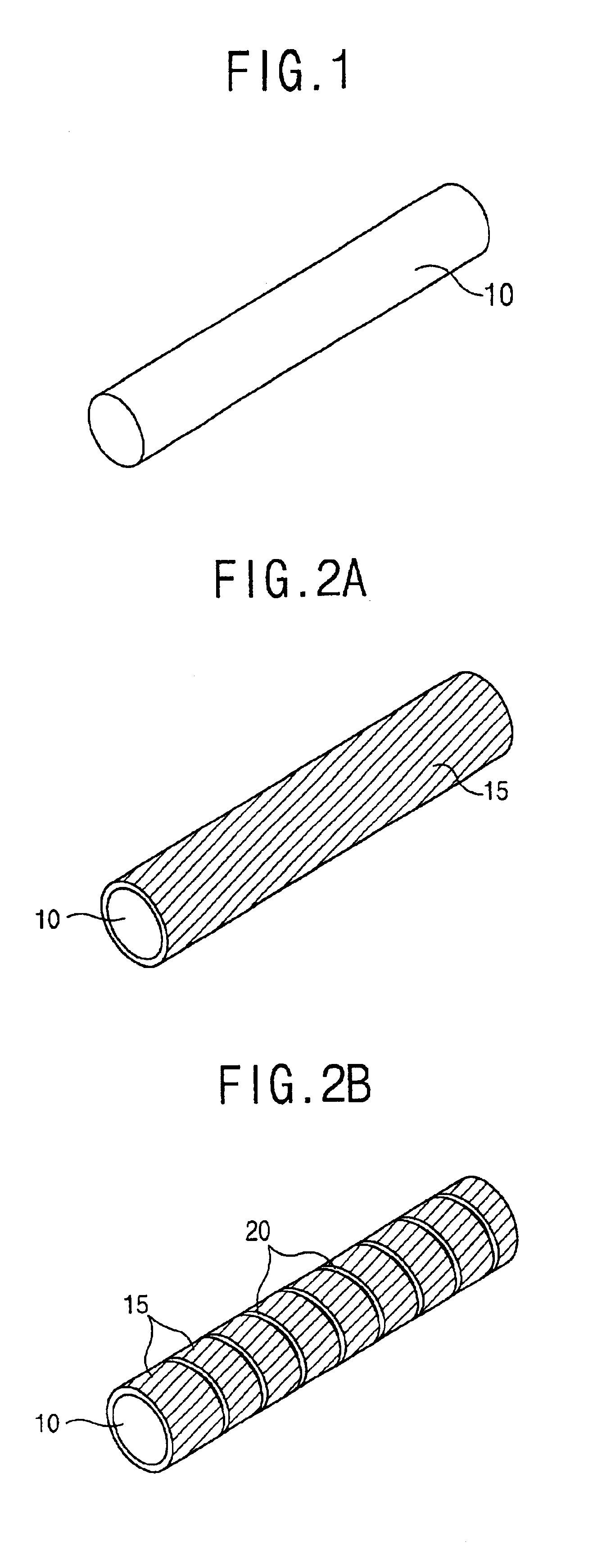
[0029]First, as an inductor main body, ferrite or ceramic powder mixed with a thermoplastic organic binder is formed into a cylindrical shape by a process such as extruding or pressing.

[0030]A main body is formed so as to have a cylindrical shape and a coil pattern is formed at a surface of the main body. In a first example of the present invention, a metal layer is formed on a surface of the cylindrical body and a spiral coil pattern is formed on the metal layer.

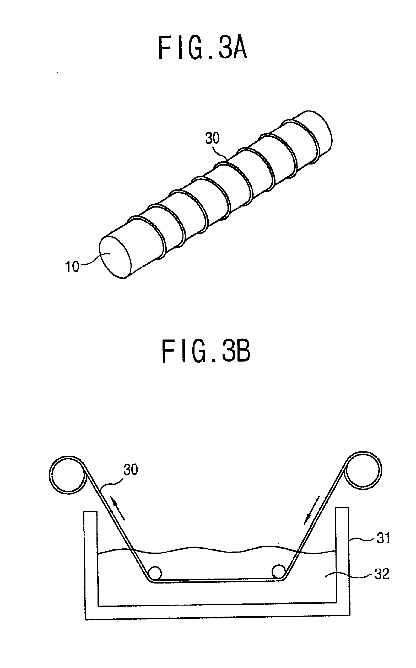
[0031]In accordance with another example of the present invention, a coil pattern is formed by winding a thread-shaped flexible material including conductive paste on the surface of the cylindrical body and hardening the conductive paste included in the flexible material.

[0032]In accordance with a still another example of the present invention, a coil pattern is formed by winding a tape having a certain thickness and a width on the surface of the cylindrical body as a spiral shape having a certain interval, coating conducti...


PUM

PropertyMeasurementUnit
temperatureaaaaaaaaaa
pressureaaaaaaaaaa
thicknessaaaaaaaaaa

Abstract

In a method for fabricating a surface mountable chip inductor, a spiral coil pattern is formed on a surface of a cylindrical body fabricated by mixing ferrite or ceramic powder with thermoplastic organic binder, the cylindrical body is transformed into a square-shaped body by being inserted into a square-shaped mold and pressure being applied at a certain temperature. An electric characteristic lowering problem can be prevented by forming the coil on the cylindrical body, and transforming the cylindrical body into a square-shaped body to improve surface mounting.

Description

BACKGROUND OF THE INVENTION[0001]1. Field of the Invention[0002]The present invention relates to a method for manufacturing a chip inductor, and in particular to a method for manufacturing a surface mountable chip inductor used for electric appliances, etc.[0003]2. Description of the Prior Art[0004]A chip inductor is used for various electric appliances such as electronic home appliances as well electronic industrial equipment, etc. Recently, responsive to miniaturization and lightweight trends of various electric appliances, electric parts for electric appliances are also being miniaturized and rendered lighter. In the meantime, as a result of the development of digital communication, the frequency being used is gradually extended to a high frequency region, and accordingly, electromagnetic interference conditions have deteriorated. Most electronic devices are surface-mounted on a printed circuit board to automate fabrication processes. However, because the surface-mounted devices ...

Claims


Application Information

Patent Timeline
Patent Type & Authority Patents(United States)
IPC IPC(8): H01F41/00H01F17/00H01F41/04H01F27/255
CPCH01F17/0033H01F41/005H01F41/041Y10T29/4902Y10T29/49071Y10T29/49076
Inventor AHN, BYEUNG-JOON
Owner CERATECH
Why Eureka
Try Eureka