Surface mount assembly system with integral label feeder

a technology of assembly system and label feeder, which is applied in the direction of mechanical control devices, instruments, process and machine control, etc., can solve the problems of inability to advance incrementally and reliably, inability to perforate linered label stock, and high cost of additional steps, so as to achieve efficient use

Inactive Publication Date: 2005-08-02
UI HLDG
View PDF27 Cites 13 Cited by
  • Summary
  • Abstract
  • Description
  • Claims
  • Application Information

AI Technical Summary

Benefits of technology

[0017]The technique described above is advantageous because it efficiently enables the use of a label feeder that may be interchanged with other component-type feeders in a pick-and-place system. The techniques make it unnecessary to have manual label application or a dedicated label-feeding station. As a result of the invention, it is possible to integrate label-feeding technology into component placement equipment.

Problems solved by technology

However, as will be appreciated, such additional steps are costly either in direct labor or as capital investments for automation.
A conventional tape feeder machine is neither suited nor adaptable to providing peeled labels ready for picking because a) it is not capable of peeling such a label from a continuous backing liner, b) a peeled label in presentation position for acquisition by a pick-and-place machine will adhere unacceptably to the tape, and c) the label must be positioned in a close-tolerance, consistent manner in order to allow for accurate retrieval and placement by the pick and place machine in the same manner as components are retrieved and placed.
Further, commonly available linered label stock is not perforated and thus cannot be advanced incrementally and reliably if simply substituted for the tape in a tape feeder machine.
Peeled labels may exhibit substantial curl, and thus the spatial location of such a label may not be precisely controlled.
Known lips of linered label printers, therefore, are inherently inadequate to meet the high-tolerance label positioning requirements of an automatic pick-and-place machine.
The techniques make it unnecessary to have manual label application or a dedicated label-feeding station.

Method used


Image

  • Surface mount assembly system with integral label feeder
  • Surface mount assembly system with integral label feeder
  • Surface mount assembly system with integral label feeder

Examples


Embodiment Construction

[0029]For a general understanding of the present invention, reference is made to the drawings. In the drawings, like reference numerals have been used throughout to designate identical elements.

[0030]As used herein, the term “label” includes self-adhering, flexible labels that are available in roll stock, as well as other similarly characterized components that may be temporarily placed or adhered to a self-adhesive backing tape and are suitable for peelable release therefrom. The term label specifically includes other components such as die-electric shields and interposers well known in surface mount technology.

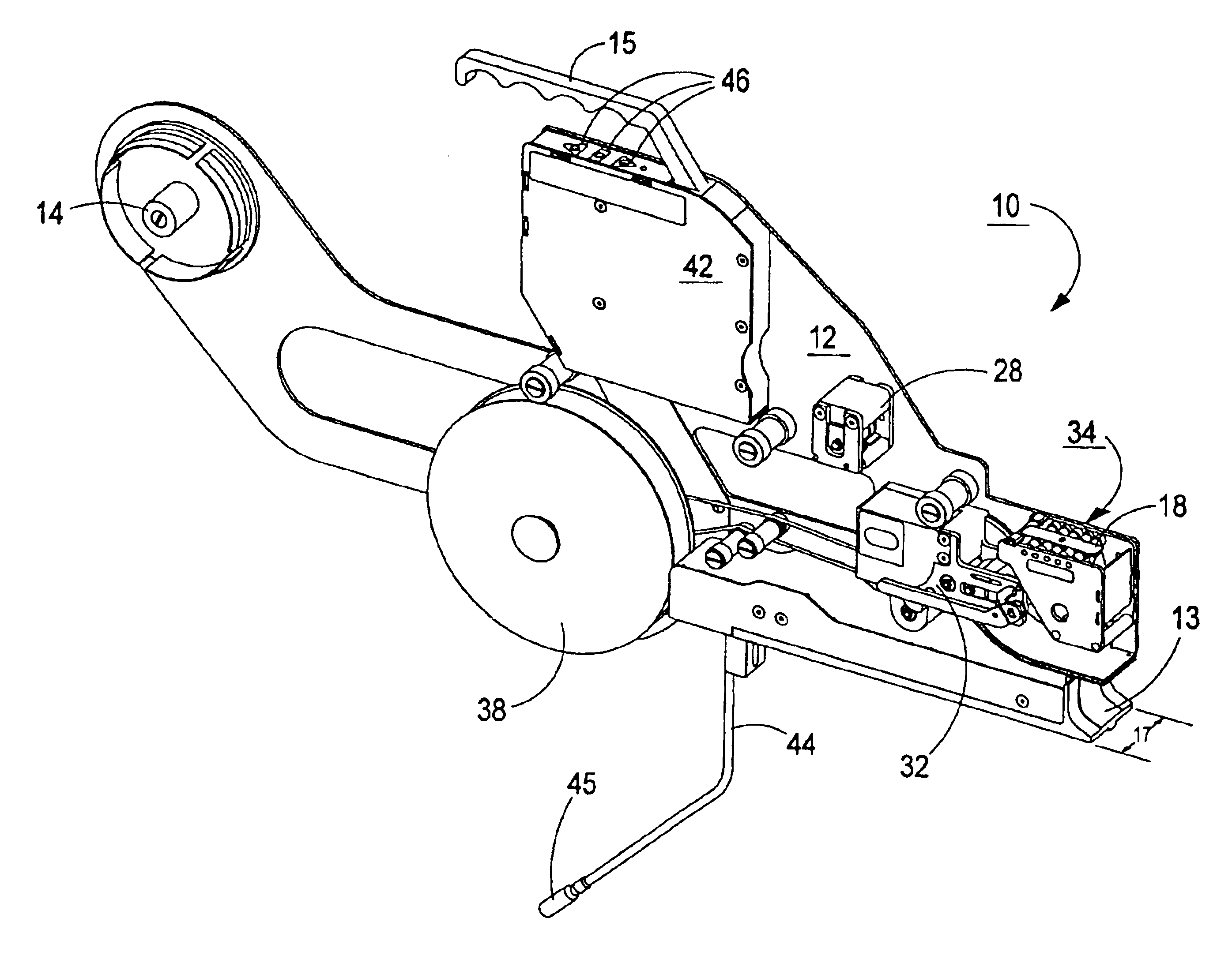
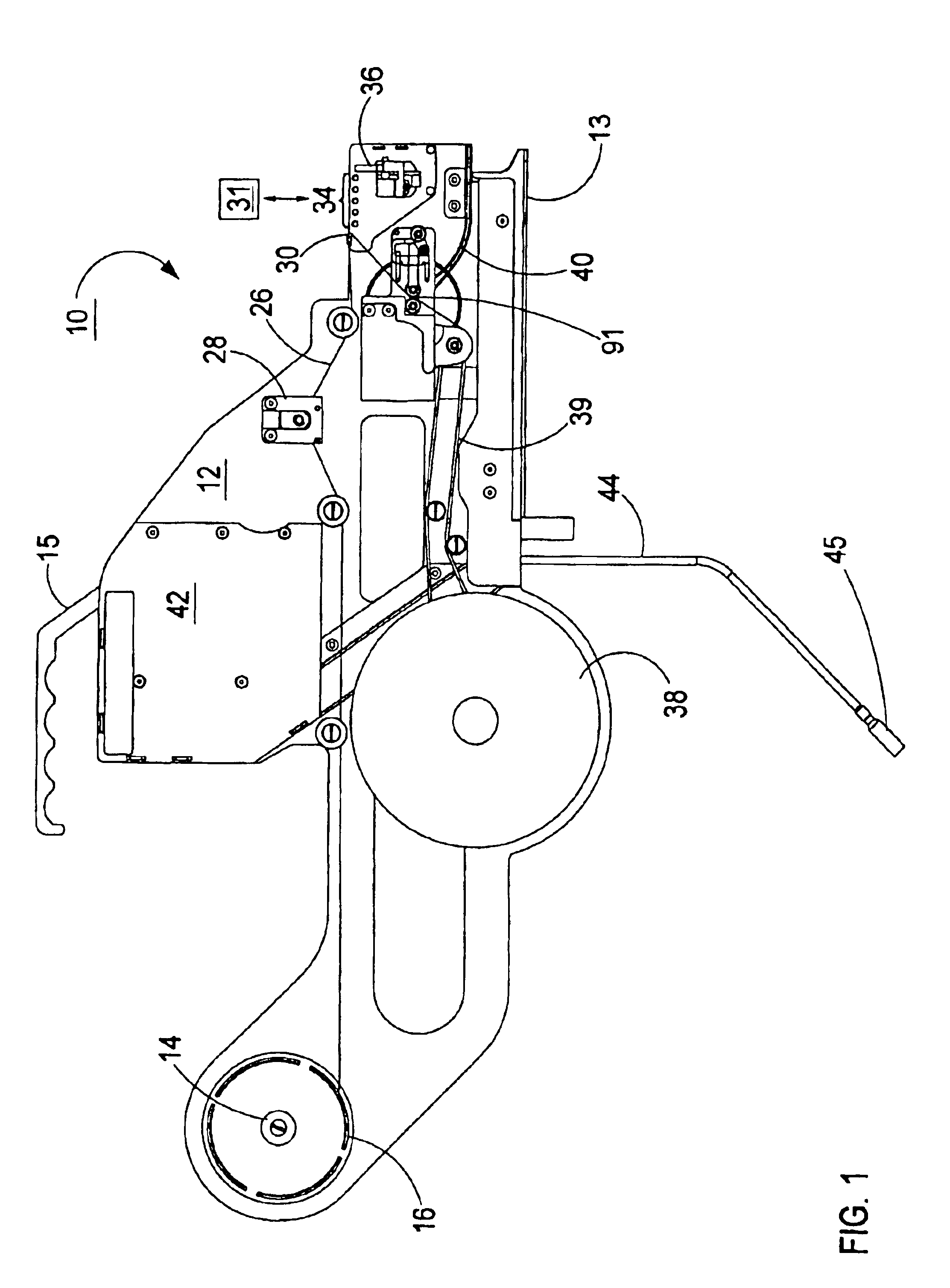
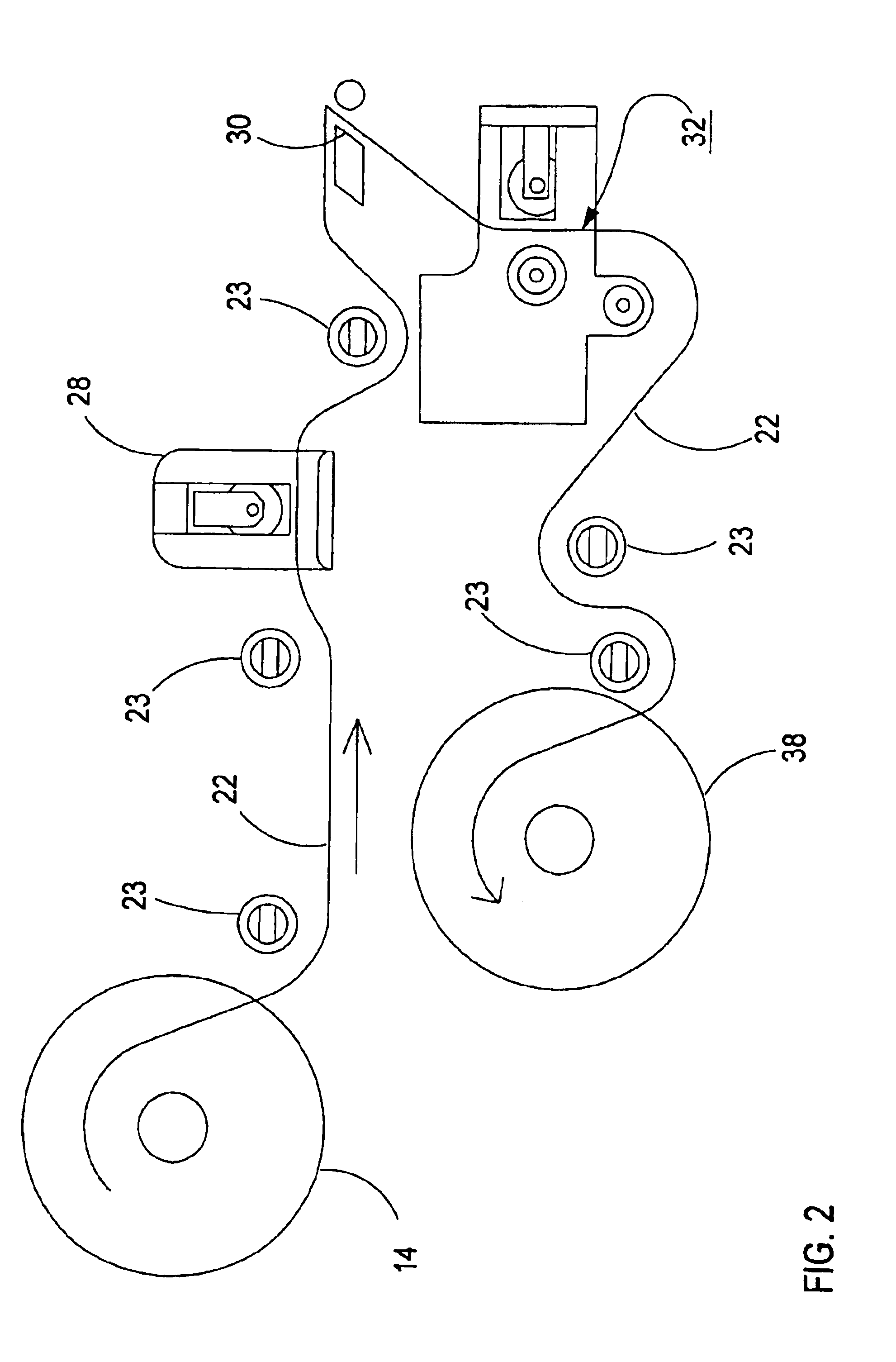
[0031]Referring to FIGS. 1 through 4, a label feeder 10 in accordance with the invention has a vertical frame 12, formed preferably from sheet metal stock, for supporting components of the feeder. Frame 12 is provided with a shoe 13 for engagement with a mating fixture (not shown) on a pick-and-place machine (not shown), and a handle 15 for ease in manual transport and insta...


PUM

PropertyMeasurementUnit
widthaaaaaaaaaa
angleaaaaaaaaaa
included angleaaaaaaaaaa

Abstract

The present invention is a method and apparatus conveying a roll of liner stock bearing removably adhered components such as labels. The liner is pulled through the feeder by a capstan drive having opposed fluted nip rollers driven by a stepper motor. Advance of the stepper motor is controlled by a programmable electronic controller. The linered labels are led through a tensioner and around an acute-angle peeler edge which separates the labels from the liner. The peeling action advances a label onto a platform comprising a bed of rollers having an inherently low-adherence surface. Preferably the rollers are undercut to form circumferential ridges and reduce the surface area in contact with the label adhesive and to minimize adherence thereto. When peeling of a label is completed, the label has been advanced onto the roller bed to precisely the proper location for acquisition by a pick-and-place machine. The presence of a label on the platform is confirmed by a sensor that signals the controller to stop further liner advance. The signal also serves to reset the feeder for advance of the next label after the first label is picked from the roller bed.

Description

[0001]This application is a continuation of pending U.S. application Ser. No. 09 / 550,030, filed Apr. 14, 2000 by Peter Davis et al., which is a continuation-in-part of pending U.S. application Ser. No. 09 / 028,790 for a “LABEL FEEDER,” filed Feb. 24, 1998 by Peter Davis et al., the entire contents of which are hereby incorporated by reference.[0002]This invention relates generally to a method and apparatus for feeding adhesive-backed components in a surface mount assembly system. More particularly, the invention is an apparatus and method for peeling and feeding labels and other thin components, including automatically peeling labels and similar components from liner stock and presenting them sequentially on a non-adherable platform for acquisition, on a non-adhesive side by a vacuum-operated, pick-and-place robotic head.[0003]A portion of the disclosure of this patent document contains material that is subject to copyright protection. The copyright owner has no objection to the facs...

Claims


Application Information

Patent Timeline
Patent Type & Authority Patents(United States)
IPC IPC(8): B65C9/42B65C9/08B65C9/00B65C9/18H05K13/04H05K13/02B44C1/00
CPCB65C9/1865B65C9/1884B65C9/42H05K13/021H05K13/0469Y10T156/1707Y10T156/171Y10T156/1744Y10T156/1195Y10T156/1768Y10T156/1994Y10T156/1705H05K13/0417
Inventor DAVIS, PETERHOWE, RICHARDLYNDAKER, DAVID W.PROCTOR, SCOTT
Owner UI HLDG
Why Eureka
Try Eureka