Dual-rotor, radial-flux, toroidally-wound, permanent-magnet machine

a permanent magnet machine and radial-flux technology, applied in the field of electric machines, can solve the problems of induction machines with their own drawbacks and disadvantages, decrease the efficiency of motors, and reduce the efficiency of motors, and achieve the effects of low machine cost, high torque density, and high efficiency

Inactive Publication Date: 2005-08-02
WISCONSIN ALUMNI RES FOUND
View PDF18 Cites 111 Cited by
  • Summary
  • Abstract
  • Description
  • Claims
  • Application Information

AI Technical Summary

Benefits of technology

[0010]The present invention relates to a novel machine family of dual-rotor, radial-flux, toroidally-wound, permanent-magnet machines. The dual-rotor, radial-flux machines of the present invention can possess a variety of embodiments based on differ

Problems solved by technology

However, induction machines have their drawbacks.
Rotor windings are present in all induction machines, rotor current produces rotor resistive losses, decreasing the efficiency of the motor, particularly at low power ratings, and cause cooling problems.
However, these all have their own drawbacks and disadvantages.
However, rare

Method used


Image

  • Dual-rotor, radial-flux, toroidally-wound, permanent-magnet machine
  • Dual-rotor, radial-flux, toroidally-wound, permanent-magnet machine
  • Dual-rotor, radial-flux, toroidally-wound, permanent-magnet machine

Examples


Embodiment Construction

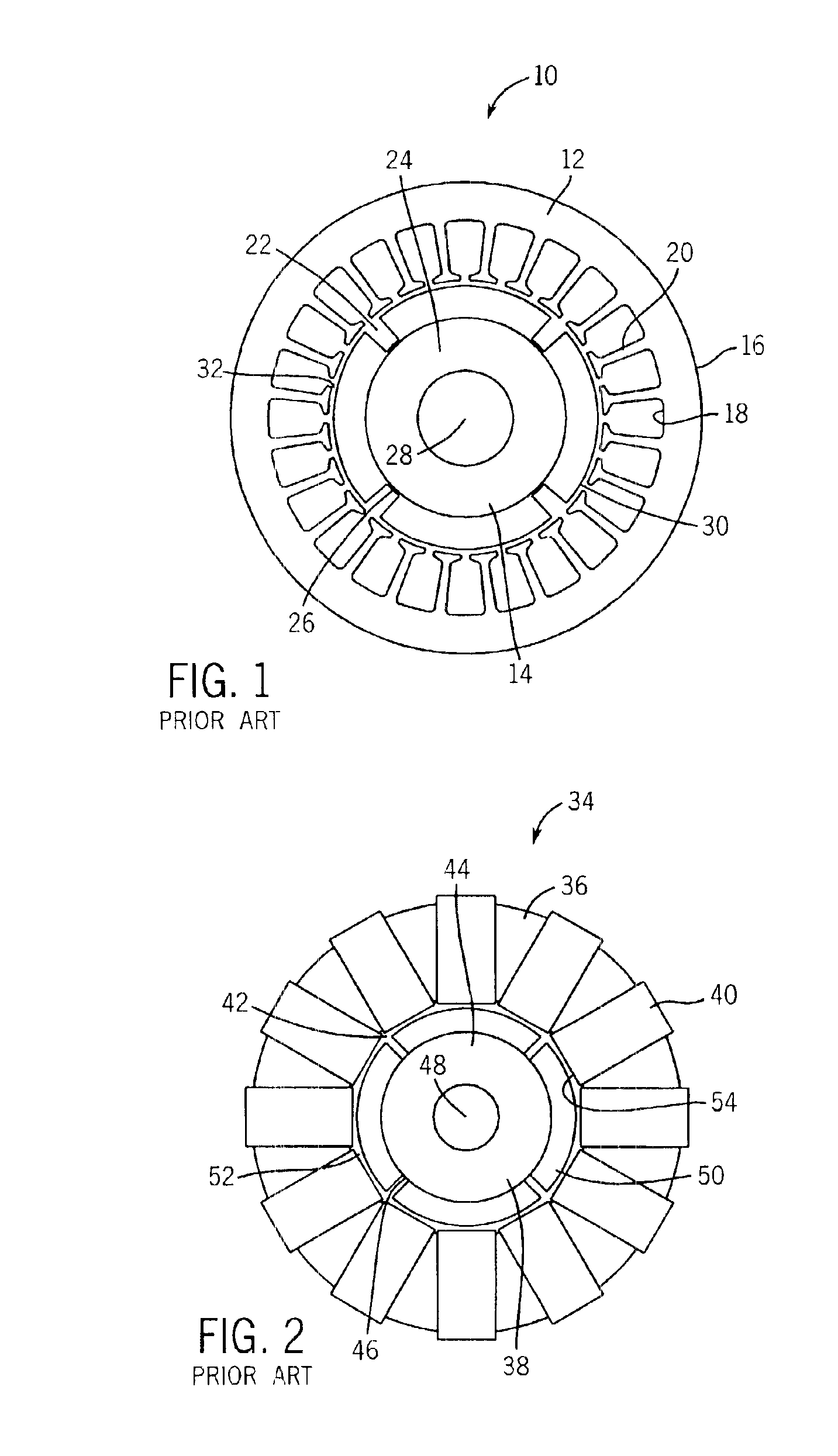
[0040]Referring now to the drawings, FIG. 1 illustrates a prior art radial-flux, surface-mounted, slotted, permanent magnet machine 10. The machine 10 includes a stator 12 and a permanent magnet rotor 14. The stator 12, which is of a generally cylindrical shape, is external to the rotor 14 and includes an outer surface 16 and an inner surface 18. The inner surface 18 includes a plurality of radially inwardly extending teeth 20 to receive polyphase windings of electrical wires wound around the teeth 20. The stator 12 further includes a central opening 22 in the middle of the stator for receiving the rotor 14 therein. The rotor 14, which is also of a generally cylindrical shape, includes a magnetically permeable core 24 with an outer surface 26 and a central opening 28 for receiving the shaft of a motor therein. A plurality of permanent magnets 30 are mounted to the outer surface 26 of the rotor 14. An air gap 32 is formed between the permanent magnets 30 and the teeth 20 of the stato...


PUM


Abstract

The present invention provides a novel dual-rotor, radial-flux, toroidally-wound, permanent-magnet machine. The present invention improves electrical machine torque density and efficiency. At least one concentric surface-mounted permanent magnet dual-rotor is located inside and outside of a torus-shaped stator with back-to-back windings, respectively. The machine substantially improves machine efficiency by reducing the end windings and boosts the torque density by at least doubling the air gap and optimizing the machine aspect ratio.

Description

STATEMENT REGARDING FEDERALLY SPONSORED RESEARCH OR DEVELOPMENT[0001]This invention was made with United States Government support awarded by the Department of Energy (DOE), Grant No. DE-AC36-99-GO10337. The United States Government has certain rights in this invention.BACKGROUND OF THE INVENTION[0002]The present invention relates generally to electrical machines, and more particularly to a dual-rotor, radial-flux, toroidally-wound, permanent magnet machine.[0003]Electrical machines that transform mechanical energy into electrical energy have been studied, designed and utilized for over a century. Today, electrical machines are widely used in every aspect of human life. Electrical machines may take the form of DC motors or AC motors. DC motors have been in use for a long time due to their high performance in motion and drive applications. With the development of power electronics, new control technology and machine topologies, great progress has been made to replace DC machines in t...

Claims


Application Information

Patent Timeline
IPC IPC(8): H02K21/16H02K21/22
CPCH02K21/16H02K21/222H02K21/12H02K21/14H02K21/22
Inventor QU, RONGHAILIPO, THOMAS A.
Owner WISCONSIN ALUMNI RES FOUND
Why Eureka
Try Eureka