Wavelength controllable optical device and light control method

a controllable optical and wavelength technology, applied in the direction of optical elements, instruments, semiconductor lasers, etc., can solve problems such as complex adjustmen

Inactive Publication Date: 2005-08-02
FUJITSU LTD
View PDF5 Cites 4 Cited by
  • Summary
  • Abstract
  • Description
  • Claims
  • Application Information

AI Technical Summary

Benefits of technology

[0016]An object of this invention is to provide a wavelength controllable optical device capable of configuring a wavelength variable laser oscillator which is easy to control and has a fast response speed.

Problems solved by technology

However, adjustment becomes complicated because the refractive indices of both one reflector region 110 and the phase adjusting region 112 are to be adjusted.

Method used


Image

  • Wavelength controllable optical device and light control method
  • Wavelength controllable optical device and light control method
  • Wavelength controllable optical device and light control method

Examples


first embodiment

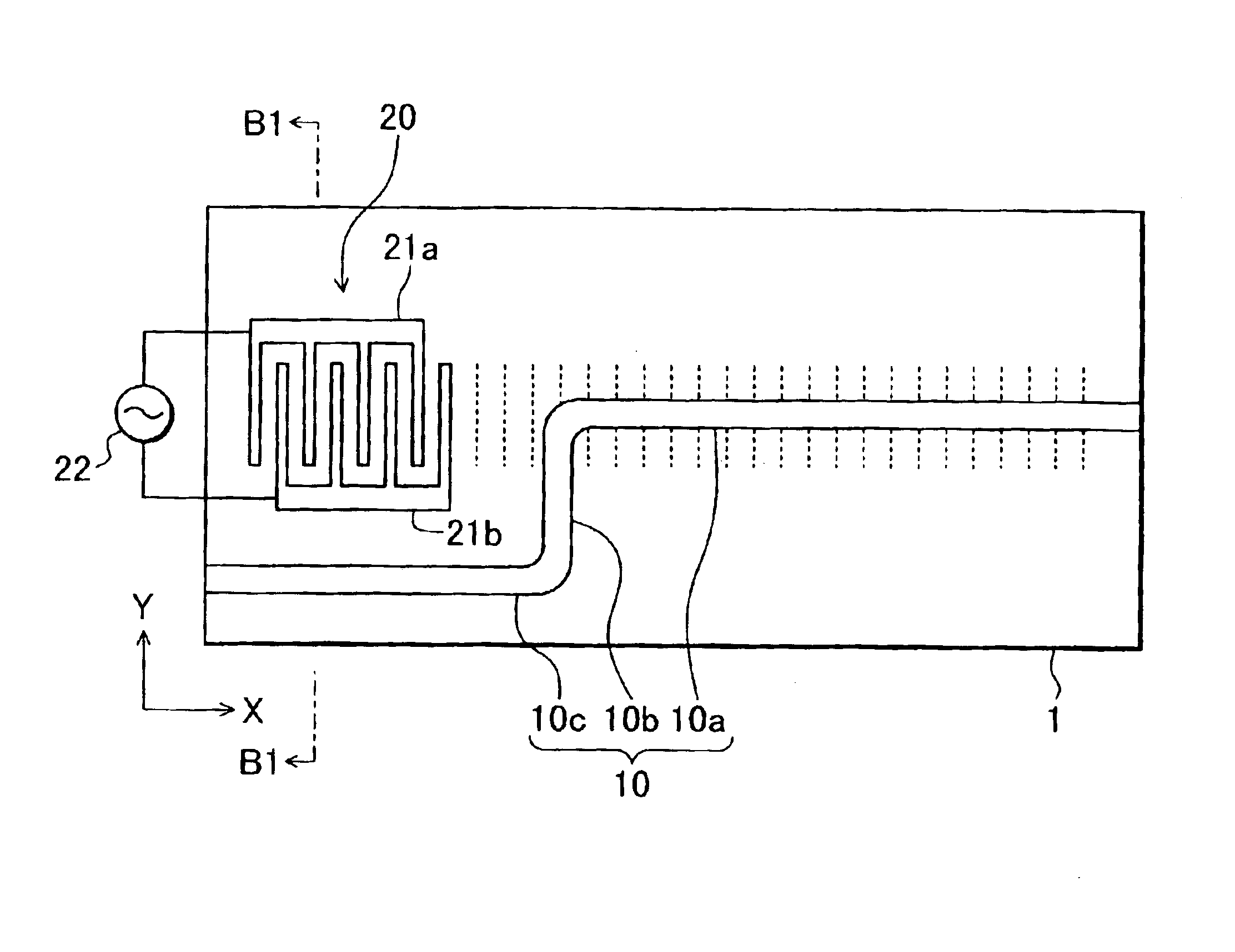
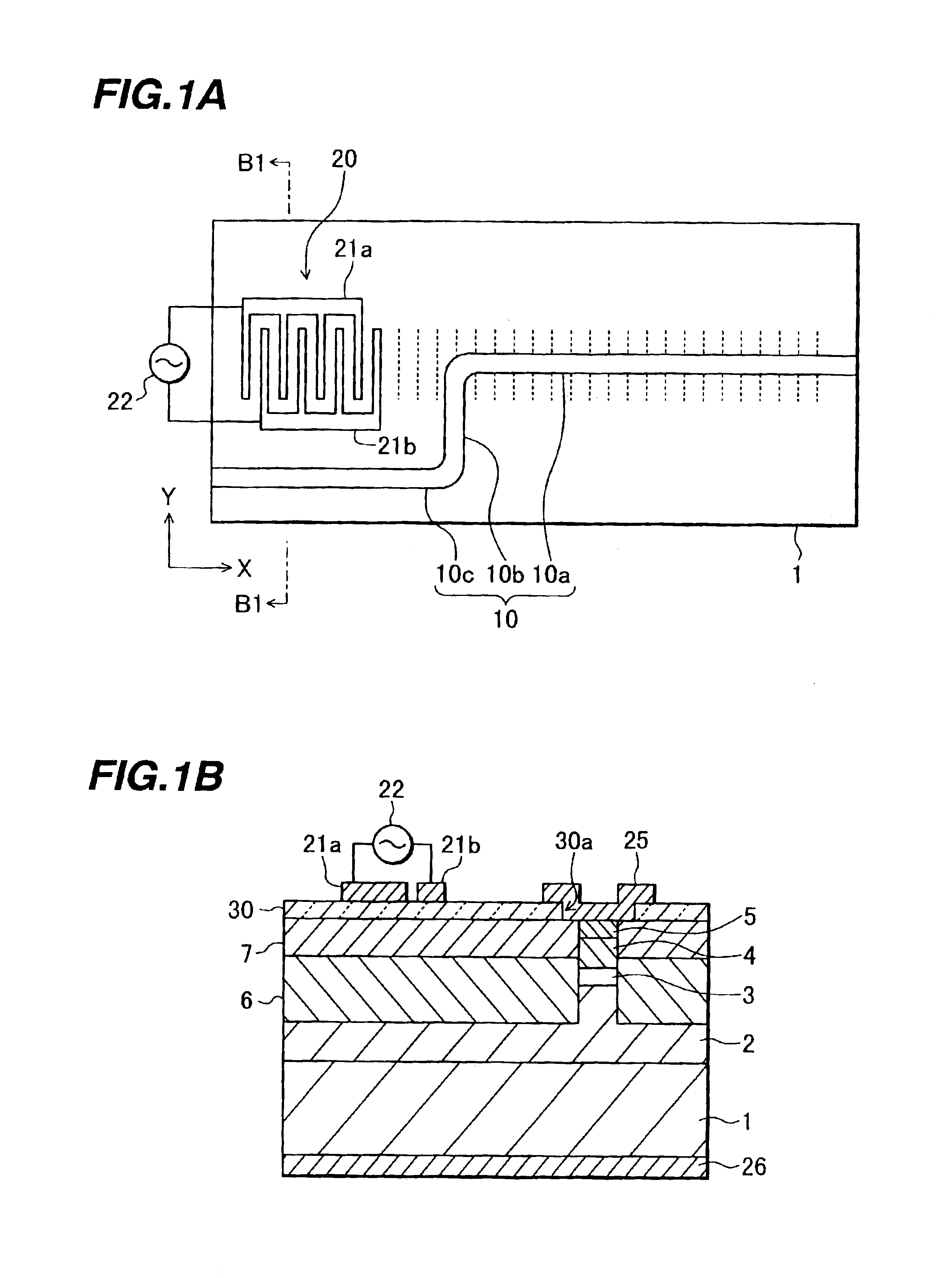
[0024]A plan view of a wavelength variable laser oscillator according to the invention is shown in FIG. 1A. On the surface of a substrate 1 of n-type InP, an optical waveguide 10 of InGaAsP is formed. The optical waveguide 10 is constituted of a linear first region 10a, a linear second region 10b and a linear third region 10c and has a width of about 3 μm. The first and third regions 10a and 10c extend in an X-axis direction (in a crosswise direction in FIG. 1A) and the second region 10b extends in a Y-axis direction (in a lengthwise direction in FIG. 1A). The first to third regions 10a to 10c are smoothly coupled in this order and have a plan shape like a crank bent at right angles. The lengths of the first to third regions 10a to 10c are 10 mm, 2 mm and 4 mm, respectively.

[0025]A high reflective film is formed on the end face of the optical waveguide 10 on the third region 10c side and a low reflective film is formed on the end face of the optical waveguide 10 on the first region ...

second embodiment

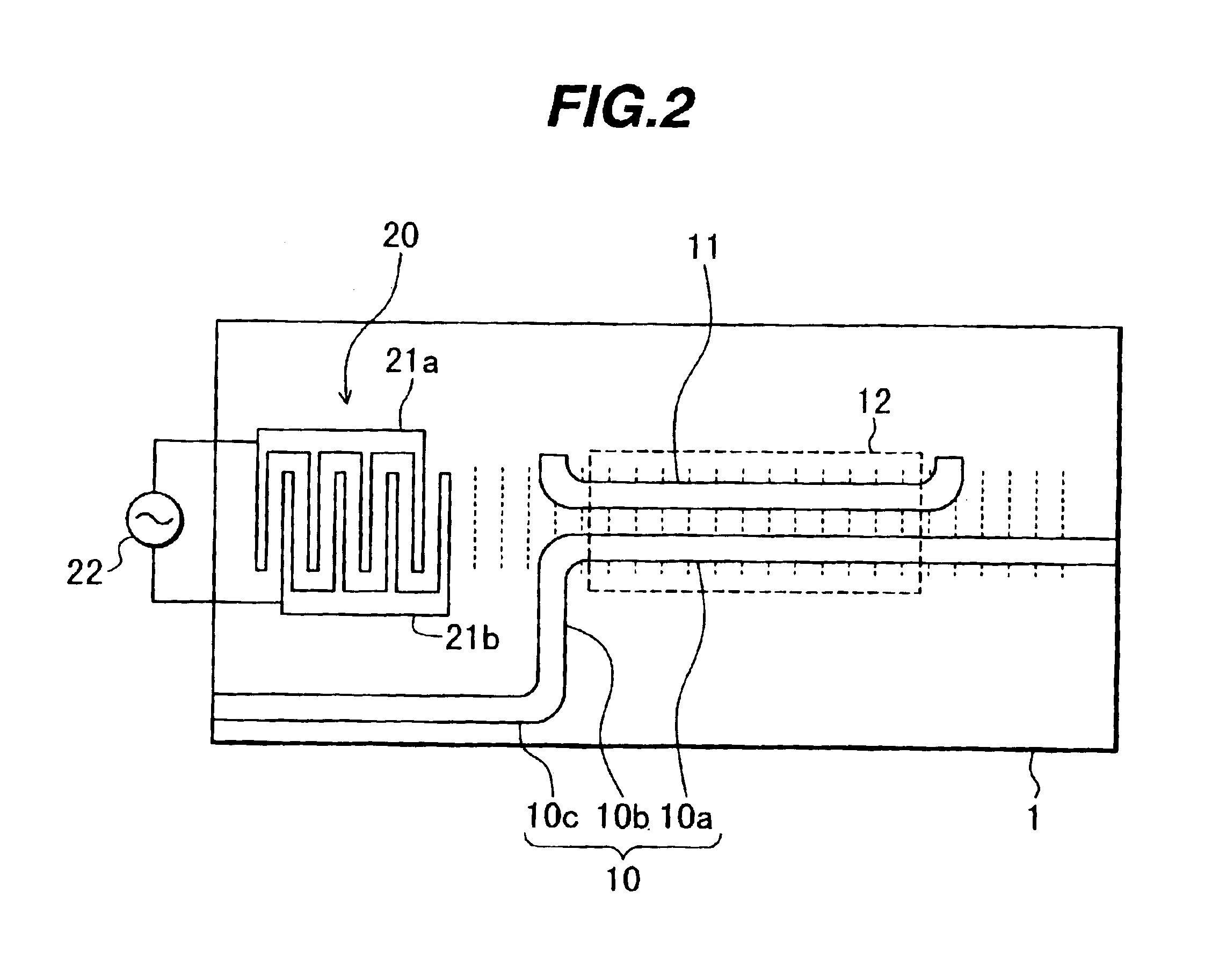
[0039]In the second embodiment, at the side of the first region 10a of the optical waveguide 10, another optical waveguide 11 is disposed. A distance between the optical waveguides 10 and 11 is about 1 μm and the two optical waveguides constitute a directional coupler 12. The optical waveguide 11 is formed by the same processes as those of forming the optical waveguide 10, and the lamination structures of the two optical waveguides are the same.

[0040]A surface acoustic wave excited by the surface acoustic wave transducer 20 propagates through the first region 10a of the optical waveguide 10 and through the region where the optical waveguide 11 is disposed.

[0041]A directional coupler 12 functions as a band-pass filter. The laser oscillator oscillates at the wavelength in the band-pass range of the band pass filter. The wavelength in the band-pass range of the band pass filter changes with the wavelength of a surface acoustic wave. Therefore, by changing the frequency of the a.c. volt...


PUM

PropertyMeasurementUnit
widthaaaaaaaaaa
lengthsaaaaaaaaaa
lengthsaaaaaaaaaa

Abstract

A first optical waveguide for guiding light is formed on a substrate. A surface acoustic wave transducer for generating a surface acoustic wave which propagates along a direction in which the first optical wave guide guides the light at least partial region of the first optical waveguide, is formed on the substrate. A wavelength variable laser oscillator can be formed which is easy to control and has a fast response speed.

Description

CROSS REFERENCE TO RELATED APPLICATION[0001]This application is based on Japanese Patent Application No. 2002-074869, filed on Mar. 18, 2002, the entire contents of which are incorporated herein by reference.BACKGROUND OF THE INVENTION[0002]A) Field of the Invention[0003]The present invention relates to a wavelength controllable optical device, and more particularly to a wavelength controllable optical device suitable for application to a wavelength variable laser oscillator.[0004]B) Description of the Related Art[0005]A sampled grating laser oscillator, a vertical cavity surface emitting laser (VCSEL) integrated with a micro electro-mechanical systems (MEMS) mirror, and the like are known as wavelength variable laser oscillators.[0006]FIG. 3A is a schematic cross sectional view of a sampled grating laser oscillator. An active layer 100 is sandwiched between a lower clad layer 101 and an upper clad layer 102. Along a light propagation direction, a first reflector region 110, a gain ...

Claims


Application Information

Patent Timeline
Patent Type & Authority Patents(United States)
IPC IPC(8): G02F1/01G02F1/125H01S5/00H01S5/12H01S5/0625G02B6/12H01S5/06H01S5/50H03H9/145
CPCG02F1/125H01S5/12H01S5/06258H01S5/101H01S5/1234
Inventor AKIYAMA, TOMOYUKI
Owner FUJITSU LTD
Why Eureka
Try Eureka