Dew point hygrometers and dew sensors

a technology sensor, which is applied in the direction of material thermal analysis, instruments, and analysis by subjecting materials to chemical reactions, can solve the problems of unreliable capacitance measuring instruments, unsuitable routine work, and high cost of sensors based on dew point hygrometers. to achieve the effect of increasing the sensitivity of dew point hygrometer

Inactive Publication Date: 2005-08-09
OPTIGUIDE
View PDF37 Cites 20 Cited by
  • Summary
  • Abstract
  • Description
  • Claims
  • Application Information

AI Technical Summary

Benefits of technology

[0060]By a fourth embodiment of the invention called “condensation prism embodiment” an optical prism is placed on a thermoelectric cooler to increase the sensitivity of the dew point hygrometer. A light emitter and a light detector optically coupled through a light path defined by a least two surfaces of the prism. The humidity condenses on the surfaces of said prism, thus changing the amount of light sensed by the light detector. The thermoelectric cooler's temperature can be controlled by control mechanism, which when determining the temperature at which condensation begins to form can deform the dew point.
[0061]By a fifth embodiment of the invention termed the “capacitive dew sensor embodiment” the present invention concerns a capacitive dew sensor, in which the problem of solid contaminants (salts, dust and so on) deposited on the outside surface of the sensor and electrode's corrosion are significantly reduced by using a water layer as a one of the capacitor's electrodes.

Problems solved by technology

The second is a relative humidity meter which principle of operation is based on the change of capacity, which is very problematic when determining relatively high humidity.
Cheap instruments based on capacitance measuring are unreliable since the reading changes in time independently of changes in the humidity content of the air.
The third type of sensors are dew point hygrometers based on optic mirrors, which are very expensive, and unsuitable for routine work at greenhouse conditions since they require constant cleaning of the mirror's surface.
One of the main drawbacks of optical condensation-type dew point hygrometers is contamination by materials other than the water condensing on the cooled surface, for example, contamination by various salt solutes.
This contamination generally reduces the accuracy of the dew point measurement to a degree which depends on the amount of the contaminant present and its solubility in water.
Both soluble and insoluble materials, if allowed to build up on the condensing surface, will eventually cause the system to go out of control because of reduced mirror reflectance.
In prior art systems, heating of the mirror to the dry state for manual or automatic rebalancing of the optical detection circuit, overcomes the loop offset problem associated with reduced reflectance, but does not address the problem of measurement error associated with vapor pressure modification as induced by soluble matter.
Because most particulates circulate freely around the filter and exit the measurement chamber, the filter is slow to become contaminated.
This arrangement has a slow response time and is relatively inaccurate.
However, the problems of contaminant, due to build up of solid deposits on the surfaces of the optic fibers, is very similar to that encountered in dew point hygrometers wherein mirrors are the condensing surfaces, and is a major obstacle in providing dew point hygrometers that are accurate and reliable over long periods of time.
But such devices are electrically noisy and have changable sensitivity that depends on salts precipitanion on the sensor.
Another problem with such devices is that generally require high voltage and the explosure of the conductors and leads which features renders them vulnerable to corrosion by the weather.
The corrosion is especially rapid in the presence of high voltages used in the range of 1 to 20 volts.

Method used


Image

  • Dew point hygrometers and dew sensors
  • Dew point hygrometers and dew sensors
  • Dew point hygrometers and dew sensors

Examples


first embodiment

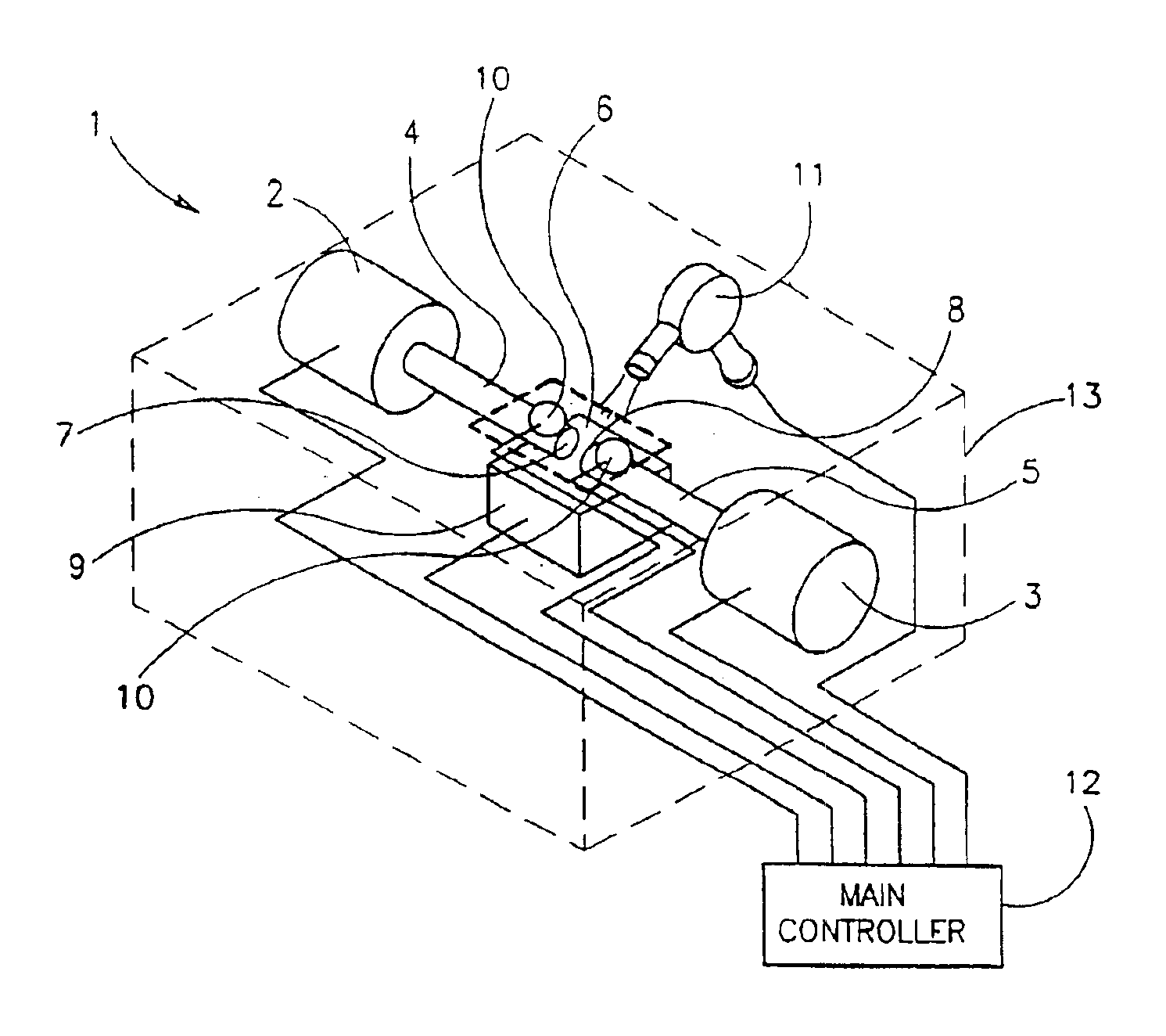
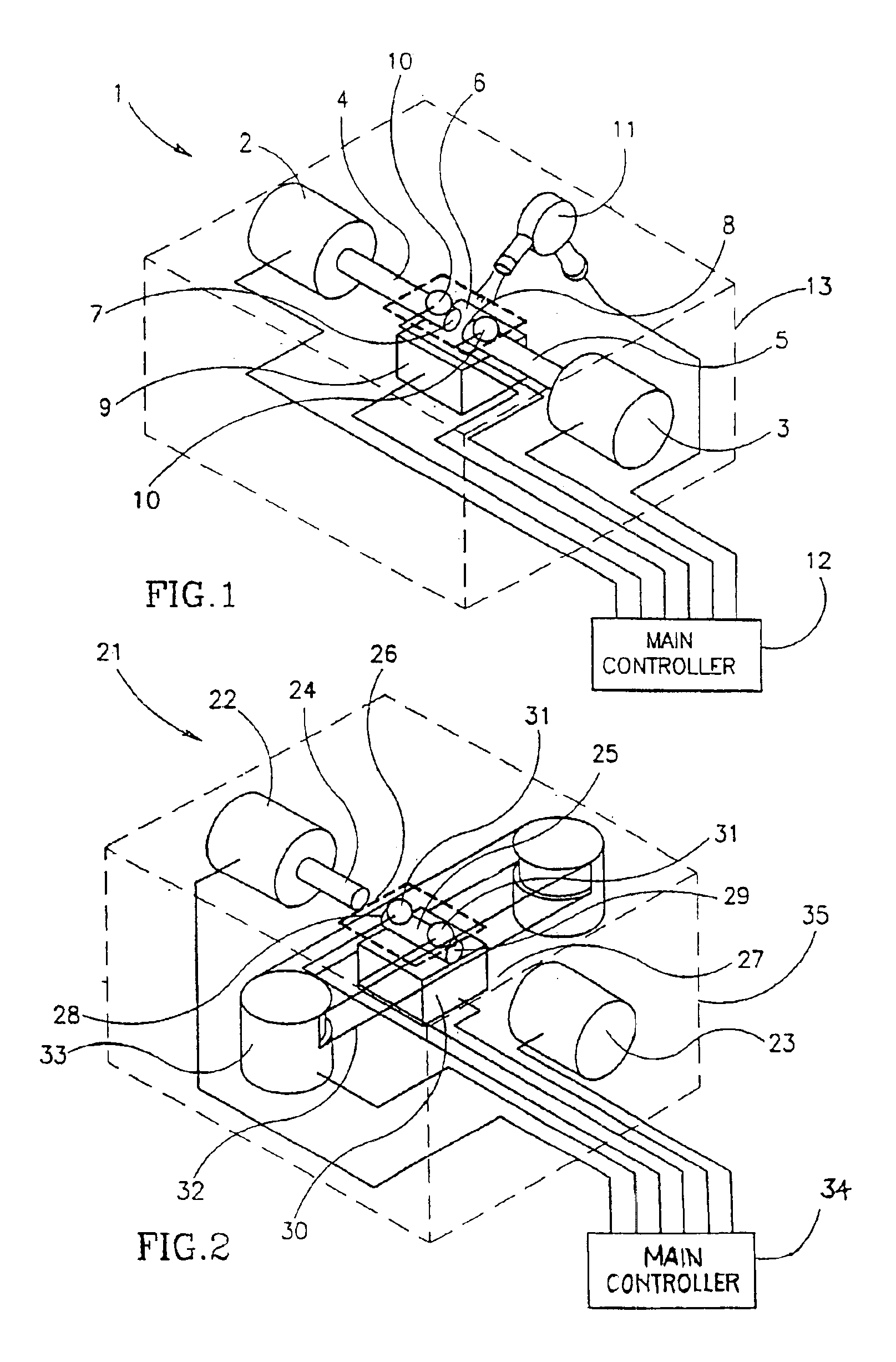
[0078]Reference is first made to FIG. 1 which shows a dew point hygrometer 1 in accordance with the first option of the invention. The hygrometer comprises a light emitter 2 for example HFBR-1524 transmitter (Hewlett Packard Components, USA), a light detector 3 for example HFBR-2524 receiver (Hewlett Packard Components, USA). Light emitter 2 and light detector 3 are coupled through a light path defined by two optic fibers, a first optic fiber 4 coupled to the light emitter and a second optic fiber 5 coupled to the light detector. Optic fibers 4 and 5 are spaced from each other so as to form sensing gap 6 therebetween. The optic fibers are for Hewlett Packard plastic fiber optic cable HFBR-PUS001 diameter 1.0 mm. (Hewlett Packard Components, USA). The uncoupled end of the first optic fiber 7 and the uncoupled end of the second optic fiber 8 serve as dew forming ends. These ends are in contact with the gas which dew point is to be determined. Formation of dew on ends 7 and 8 changes t...

second embodiment

[0093]Reference is now made to FIG. 5 which shows a fiber-optical dew sensor in accordance with the invention, for sensing the natural condensation, for example use in greenhouses. The dew sensor 80 comprises two optic fibers 81, having rough ends 88. The optic fibers have a gap therein-between 89. The optic fibers are embedded in a PVC white plate 82 which temperature is similar to the natural temperature of the ambient environment. One optic fiber 81 is connected to a light emitter 83, for example, HFBR-1524 transmitter (Hewlett Packard, Components, USA) and one optic fiber 81 is connected to a light detector 84. At night, while there is cooling, due to infrared emission of the plate 82 to the direction of the sky, the optic fibers 81 embedded in the plate are also cooled, and water condensates on the rough edges 88 of the optic fibers, filling the rough edges, and as a result the light transmitter in the optic system is increased.

[0094]An electronic control system 85 controls par...

third embodiment

[0097]Reference is now made to FIG. 6, which shows a film dew point hygrometer according to the invention, comprising a condensation film. The dew point hygrometer 90 comprises a condensation film, for example a nylon transparent film 91 placed on a thermoelectric cooler 92. The film reflects light sent from light emitter 94, through optic fiber 93 into optic fiber 95 connected to light detector 96. With the use of a fan 97, air is mobilized on the condensation film, and cools the warm side of the thermothermic cooler 92. While cooling condensation film 91, by thermoelectric cooler 92, water condensates on external side (i.e. the side facing upward) of the film and changes the light reflection from both sides of the film, which change is detected by light detector 96. Temperature sensors 98 and 99 measure the temperature of the condensation film and the air, respectively. An electronic control system 100 controls the work of the cooler 92, the light emitter 94 and the light detector...


PUM

PropertyMeasurementUnit
timeaaaaaaaaaa
voltagesaaaaaaaaaa
thicknessaaaaaaaaaa

Abstract

A dew point hygrometer for determining the dew point of a gas in which a displaceable transparent film is in contact with the gas and forms a condensation surface. The film is placed on a temperature control device controlling its temperature and an optic fiber, emits light on the film and reflected light is detected in another optic fiber, the two optical fibers being positioned at an angle with respect to the film. Condensation formed on the film changes the light transmitted by the film which is periodically displaced so that a new uncontaminated regions are exposed to the light.

Description

[0001]This application is a C-I-P of Ser. No. 09 / 830,494 filed Jul. 13, 2001 now issued as U.S. Pat. No. 6,575,621 which is a 371 of PCT / IL99 / 00571, filed Oct. 29, 1999.FIELD OF THE INVENTION[0002]The present invention concerns dew point hygrometers for determining the dew point of gas and dew sensors for determining the neutral dew condensation. More specifically the present invention concerns hygrometers comprising optic fibers, or hygrometers based on change of capacitance.BACKGROUND OF THE INVENTION[0003]State of the art hygrometers used in agriculture, notably in greenhouses, operate by usually falling into one of the following three types. The first is a psychrometer which requires a very high degree of maintenance. The second is a relative humidity meter which principle of operation is based on the change of capacity, which is very problematic when determining relatively high humidity. Cheap instruments based on capacitance measuring are unreliable since the reading changes i...

Claims


Application Information

Patent Timeline
Patent Type & Authority Patents(United States)
IPC IPC(8): G01N25/56G01N25/68
CPCG01N25/68
Inventor ZLOCHIN, IGOR
Owner OPTIGUIDE
Why Eureka
Try Eureka