Multi-purpose machine

a multi-purpose machine and workpiece technology, applied in the direction of turning equipment, milling equipment/tools, other manufacturing equipment/tools, etc., can solve the problems of rotary speed of workpieces, unfavorable tracking adjustment of tools, and region for gripping workpieces, etc., to achieve high time-saving and low level of expenditur

Inactive Publication Date: 2005-08-09
BOEHRINGER WERKZEUGMASCHEN
View PDF11 Cites 16 Cited by
  • Summary
  • Abstract
  • Description
  • Claims
  • Application Information

AI Technical Summary

Benefits of technology

[0020]Therefore the object of the present invention is to provide a method and an apparatus with which crankshafts and similar components can be machined at the relevant machining locations (big-end bearing locations, main bearing locations, side cheek side surfaces, end journal / end flange) on one machine and thus with a low level of expenditure in terms of investment items and nonetheless overall in a highly time-efficient manner.b) Attainment of the Object
[0023]The use of workpiece-based methods for the concentric surfaces already affords in that situation a very short machining time, with at the same time very good surface quality.
[0024]Using the tool-based machining methods in relation to eccentric surfaces means that the speed of rotation of the workpiece can be kept so low that optimum tracking adjustment of the tool and thus optimum accuracy to size of those surfaces is still ensured.
[0037]If it is exclusively the machining of individual items that is intended or if the machining time plays only a highly subordinate part, it is possible to deviate from the above-described idea for attaining the object of the invention, in that the eccentric rotationally symmetrical surfaces are machined with a workpiece-based machining method such as for example turning, in spite of the drive afforded during machining thereof, by way of the slow spindle drive. As described hereinbefore in regard to machining of the end region which is accommodated in the fast spindle chuck but which can be only slowly driven, that overall very greatly increases the machining time for the big-end bearings and thus the crankshaft and in addition cutting materials which are suitable for that low cutting speed such as for example HSS-cutting edges must be used.
[0038]The advantage of such a procedure however, viewed from the mechanical engineering point of view, is that the same machining method is used for big-end and main bearings, even if at greatly different cutting speeds, and consequently with the necessity for different cutting materials. Those cutting edges which consist of different material can either consist, as described above, of two separate tool units, more specifically for example cutting edges of ceramic cutting materials on a main tool body and HSS-cutting edges on the other main tool body. Both tool systems however require the same possible movements (besides displacement in the X- and Z-direction, either a pivotal movement about the C2-axis or displacement in the Y-direction) and consequently can be of an identical structure and can be equipped with an identical control system, which reduces costs.

Problems solved by technology

In addition machining operations on the end journals or end flanges (of small or large outside diameter respectively) which are admittedly concentric but which represent the end region and thus the region for gripping the workpiece in chucks represent a difficulty, and similarly for machining side cheek side surfaces, which involves the removal of large amounts of material.
When using workpiece-based methods—in order to achieve a high cutting speed and thus efficient machining—the workpiece would rotate so fast that tracking adjustment of the tool would not be a viable option or the rotary speeds of the workpiece, which can be achieved in that way, and thus the cutting speeds, would not be competitive.
In that respect the extremely different rotary speed ranges to be implemented for the workpiece drive represented the one major problem and machining of the end regions of the crankshaft represented the other major problem.

Method used


Image

  • Multi-purpose machine
  • Multi-purpose machine
  • Multi-purpose machine

Examples


Embodiment Construction

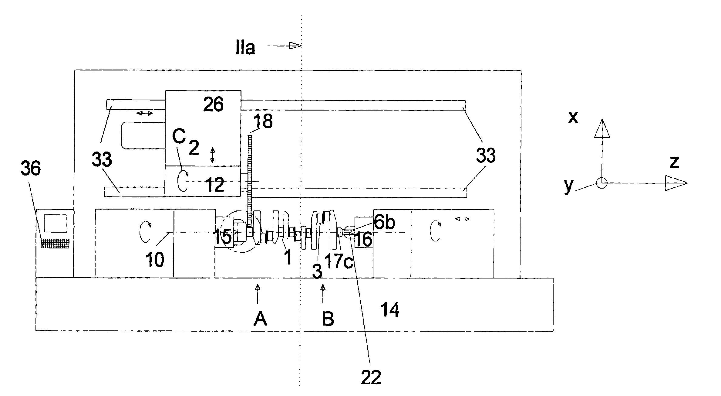
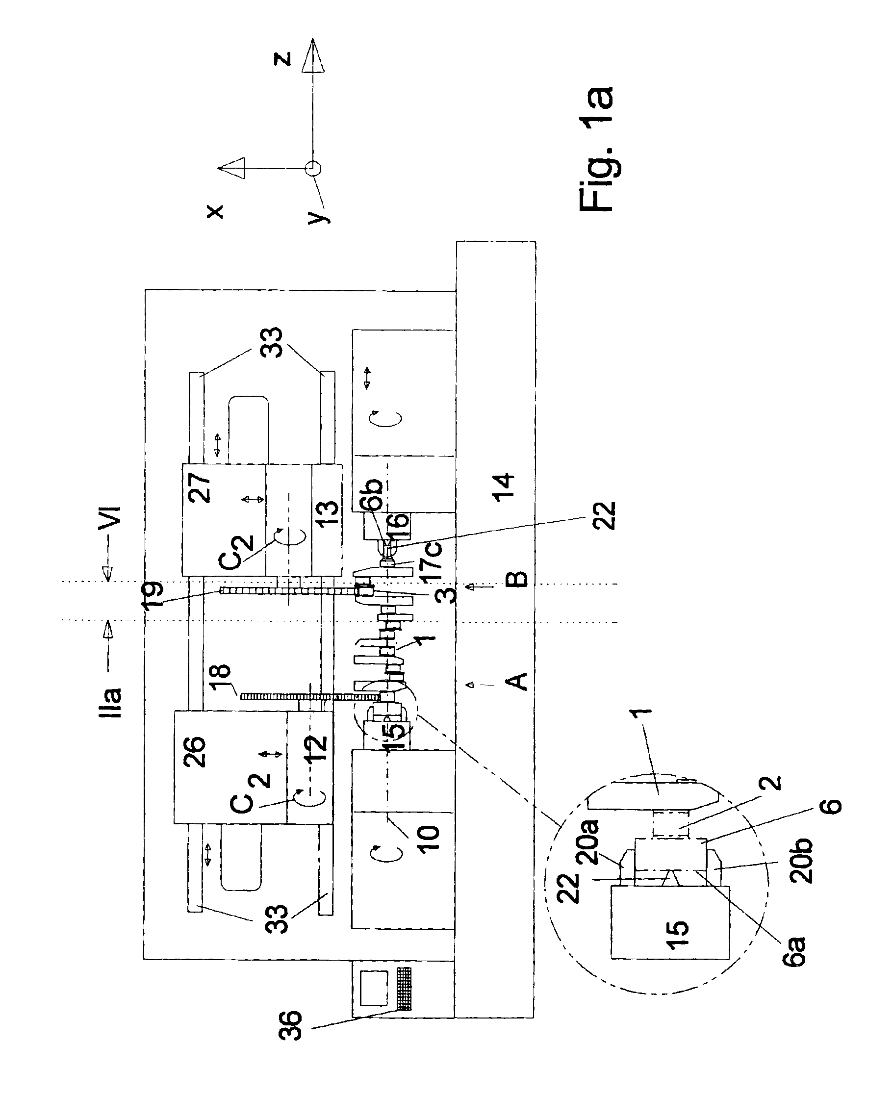
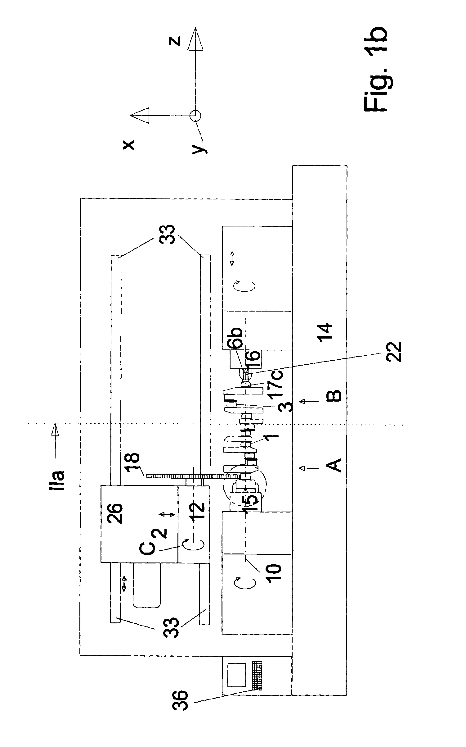
[0053]FIG. 1a shows a machine tool which accommodates drivably in rotation at its end region and machines a workpiece, for example the illustrated crankshaft 1 which includes both concentric surfaces 2, for example main bearing locations, and also eccentric surfaces 3, for example big-end bearing locations.

[0054]In this case the axial end regions of the workpiece are received in the receiving devices of two oppositely directed, mutually aligned spindles 15, 16. The receiving devices used are both jaw chucks 20 and 21 respectively and also centering points 22, 23 which are arranged at each of the spindles 15, 16.

[0055]The spindles 15, 16 are arranged on the bed 14 of the machine, like the tool supports 12, 13 which each carry a respective tool unit which is drivable in rotation about an axis (C2-axis) which is parallel to the axis of rotation (Z-axis) of the workpiece.

[0056]In addition the tool supports 12, 13 are displaceable in a defined fashion in the X-direction, that is to say t...


PUM

PropertyMeasurementUnit
rotationaaaaaaaaaa
angleaaaaaaaaaa
angleaaaaaaaaaa

Abstract

The invention concerns a method and an apparatus in which crankshafts and similar components can be machined at the relevant machining locations (big-end bearing locations, main bearing locations, side cheek side surfaces, end journal / end flange) on one machine and thus with a low level of expenditure in terms of investment items and nonetheless overall in highly time-efficient manner, by mechanical material removal in one and the same machine, wherein in all machining steps the workpiece is gripped on the central axis and is drivable in rotation and the concentric rotationally symmetrical surfaces are machined by workpiece-based methods.

Description

CROSS-REFERENCE TO RELATED APPLICATION[0001]This is a United States National Phase Application of PCT application Ser. No. PCT / EP01 / 12247 entitled “Combination Machine” which has an International filing date of 23 Oct. 2001 and which claims priority to German Application No. 10052443.5 filed 23 Oct. 2000.BACKGROUND OF THE INVENTION[0002]The invention concerns the machining of workpieces by means of material-removing, preferably mechanically material-removing, methods and apparatuses in that respect, wherein the workpieces include rotationally symmetrical surfaces which are arranged both concentrically and also eccentrically with respect to the central axis of the workpiece, and possibly end faces extending beyond same, which are to be machined.[0003]A typical workpiece of that kind is crankshafts in which the peripheral surfaces of the main bearings represent the concentric rotationally symmetrical surfaces and the peripheral surfaces of the big-end bearings represent the eccentric ...

Claims


Application Information

Patent Timeline
Patent Type & Authority Patents(United States)
IPC IPC(8): B24B5/00B24B5/42B23B5/22B23C3/06
CPCB24B5/42
Inventor HORSKY, ANTONSCHARPF, PAUL DIETERVOSS, WOLF-DIETRICH
Owner BOEHRINGER WERKZEUGMASCHEN
Why Eureka
Try Eureka