
Optical encoder

a technology of optical encoder and encoder, which is applied in the direction of coding, pulse technique, instruments, etc., can solve the problems of great disadvantage in heat resistance and oil resistance, large disadvantage in oil resistance (resistance to oily substances), and achieve excellent resistance to high-temperature steam

Active Publication Date: 2005-08-09
FANUC LTD
View PDF15 Cites 11 Cited by
  • Summary
  • Abstract
  • Description
  • Claims
  • Application Information

AI Technical Summary

Benefits of technology

[0015]The resin material may be selected from polyetherimide, polyethersulfone and polyphenylsulfone. These materials show high spectral transmittance in a range between 800 nm and 1000 nm and have excellent resistance against high-temperature steam, cutting oil and the like.
[0017]Even if the materials appear to have properties unsuitable for use with an optical element requiring accuracy, there is no problem as long as the materials meet the above conditions. The present invention possesses significance in terms of broadening options of materials and enabling actual application of a specific material (polyetherimide, polyethersulfone or polyphenylsulfone) as listed above, which is excellent in environmental resistance.

Problems solved by technology

However, resins, such as polymethyl methacrylate and polycarbonate, which have been conventionally used for making code plates, have a great disadvantage in heat resistance and oil resistance (resistance against oily substances).
This disadvantage is not negligible since the optical encoder is most typically applied in the periphery of the rotary shaft of an industrial motor, which is liable to reach a considerably high temperature.
In such a place, there is fear that the optical encoder contacts high-temperature steam and cutting oil.
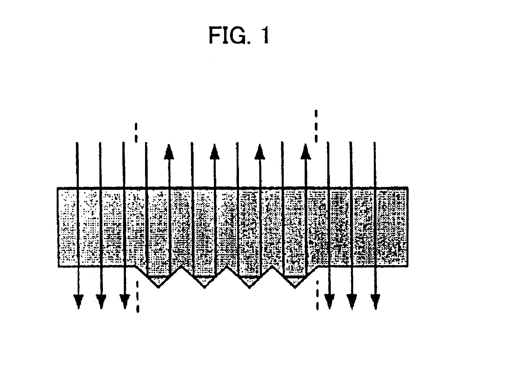
If a code plate made of polymethyl methacrylate or polycarbonate is utilized in such a harsh environment, this produces problems that the high-temperature steam and the cutting oil cause deterioration and white turbidity of the surface phase the code plate, that the surface of the code plate is melted to alter the shape of surface of the V-shaped groove, which makes it impossible to obtain a satisfactory light-and-shade contrast, and the like.
Although each of the above-described examples of prior art uses plastic as a construction material of the code plate, none of them teaches using a colored resin material.
This means that, on the level of prior art, there has not been awareness that the code plate may be formed of a colored material as long as it has sufficient spectral transmittance with respect to the wavelength of the detection light, and that it has been assumed that material used for the code plate of an optical encoder must be transparent and colorless.
Such fixed ideas have hindered free choice of material having great resistance against the high-temperature steam, cutting oil, etc.
Such a bonding construction, however, is disadvantageous in terms of costs, and moreover the bonded portion would possibly come unstuck.

Method used


Image

  • Optical encoder
  • Optical encoder
  • Optical encoder

Examples


Embodiment Construction

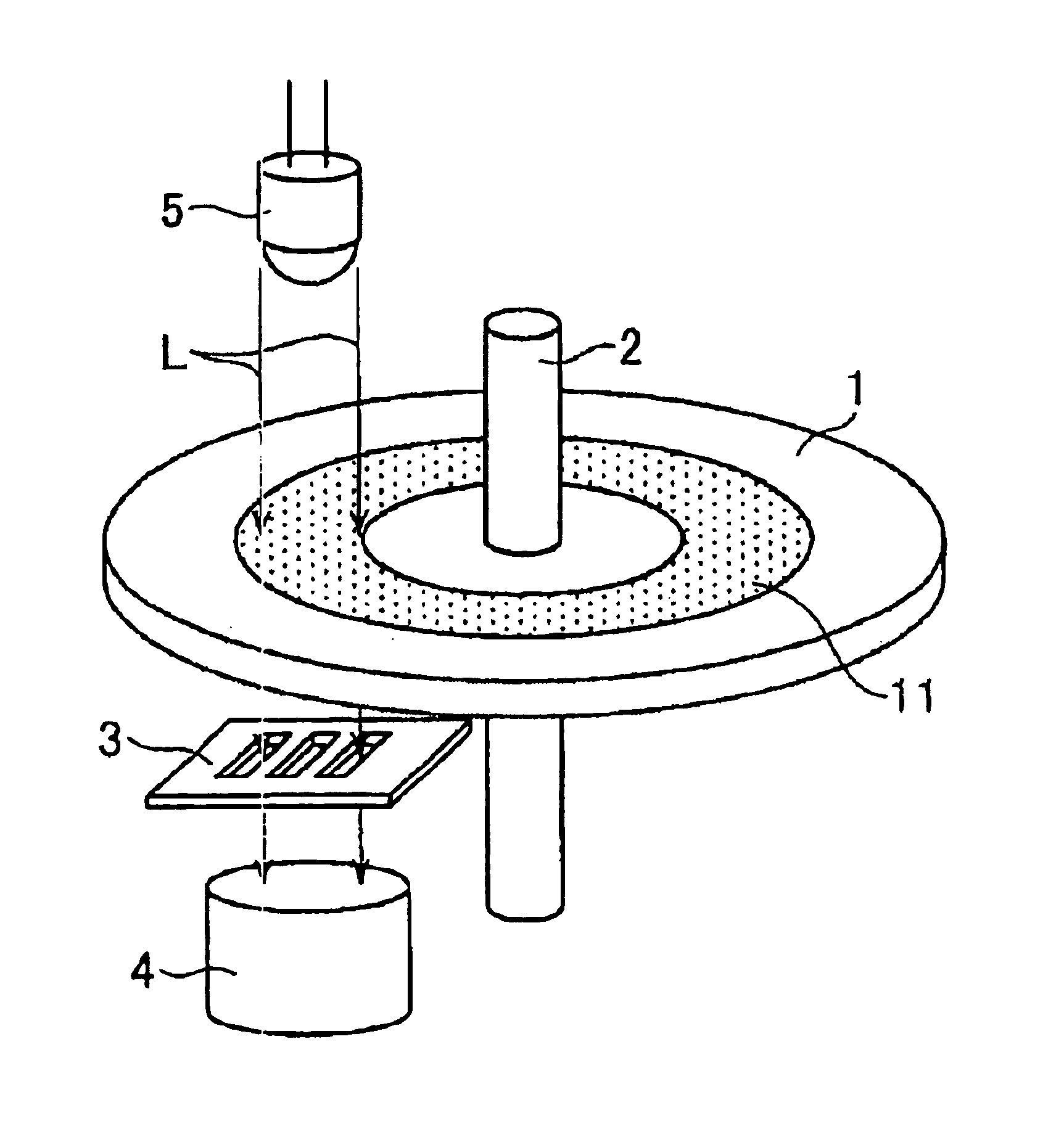
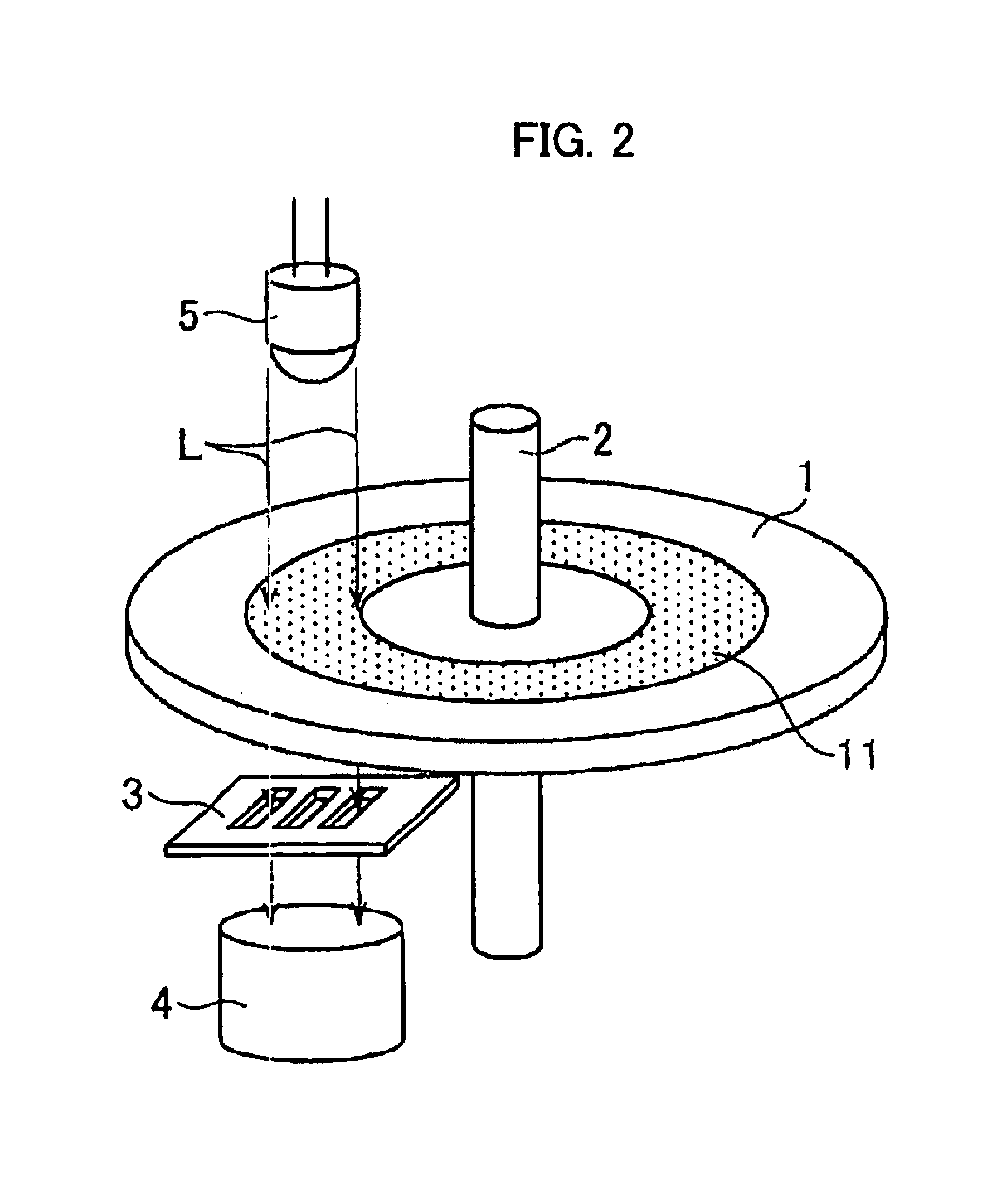
[0024]FIG. 2 is a schematic view showing one embodiment of a construction of an optical encoder to which the present invention is applied. As illustrated in FIG. 2, the optical encoder according to this embodiment is a rotary encoder comprising a code plate 1, a rotary shaft 2, a fixed slit member 3, a light-receiving unit 4, and a light-emitting unit 5 as basic components. In the light-emitting unit 5, one or more light-emitting elements, and if necessary, a lens and the like for parallelization of a beam are provided. As a light-emitting element, an infrared LED having emission wavelengths in an 800 to 1000 nm range is applied herein. The code plate 1 is provided with a code pattern having the after-mentioned aspect. The code plate 1, which is mounted on the rotary shaft 2, is so positioned that the code pattern thereof constantly intervenes between the light-emitting unit 5 and the light-receiving unit 4.

[0025]Infrared light which is supplied from the light-emitting unit 5 is mod...


PUM


Abstract

An optical encoder whose environmental resistance is improved by increasing the variety of options of materials for a resin-made code plate thereof. Used as material for at least a code pattern of the code plate of the optical encoder is one which meets the condition that the material has spectral transmittance of 70% or more with respect to detection light and that of 50% or less with respect to partial light (for example blue light) of visible wavelengths in translucent sections. If infrared light having wavelengths between 800 nm and 1000 nm is used as detection light, it is preferable to apply polyetherimide, polyethersulfone or polyphenylsulfone as a colored resin material. These materials are excellent in heat resistance, oil resistance, etc., compared to transparent and colorless materials (PMMA, PC, glass, etc.) which have been conventionally used, and hardly cause melting, deformation, white turbidity, etc., in a harsh environment.

Description

BACKGROUND OF THE INVENTION[0001]1. Field of the Invention[0002]The present invention relates to an optical encoder for use in combination with, for example a rotary shaft of a motor or the like, and more specifically to an optical encoder using a code plate formed of resin material.[0003]2. Description of the Related Art[0004]As a code plate of an optical encoder requiring high accuracy, one made of clear glass, which is provided with a pattern by chrome deposition and etching, has been conventionally utilized. In recent years, however, due to the improvement of the molding and transferring technology, an optical resin which is colorless and transparent is much more likely to be used instead of glass materials. The main reason for this is that in general resin material, compared to glass, are excellent in mass productivity because of ease of molding and have an advantage in cost for manufacturing. There are many different kinds of well-known constructions of code plates made of tra...

Claims


Application Information

Patent Timeline
Patent Type & Authority Patents(United States)
IPC IPC(8): G01D5/347G01D5/26
CPCG01D5/34707
Inventor IMAI, KEISUKETERASHIMA, HIROYA
Owner FANUC LTD
Learn More