Light stabilization for an optically excitable atomic medium

a technology of optical excitability and atomic medium, which is applied in the direction of semiconductor lasers, instruments, horology, etc., can solve the problems of complex achievement of this result, no of the older methods presently satisfactory, and the temperature of the light source and the gas cell is more difficult to control

Active Publication Date: 2005-08-09
MICROSEMI FREQUENCY & TIME
View PDF6 Cites 11 Cited by
  • Summary
  • Abstract
  • Description
  • Claims
  • Application Information

AI Technical Summary

Benefits of technology

[0022]The invention provides, in its best mode, a simple method of, and apparatus for, stabilizing the light intensity of the light source for an optically excited atomic medium over time and a range of ambient temperatures. For example, in a small, passive, gas-cell atomic frequency standard, light intensity is stabilized in such a way that the temperature sensitivity (TS) of the standard is prevented from changing with time. The invention also reduces to a negligible amount the contribution of the light shift to frequency aging (otherwise, long-term changes in light intensity due to light source aging cause frequency aging of the standard via the corresponding change in the light shift). Finally, in the case of a plasma discharge light source, the invention also provides a significant improvement in the short-term frequency stability (Allan variance) of the standard.
[0024]By sensing the D transition light transmitted by the atomic medium and providing a light intensity signal, providing an input that represents the ambient temperature that may affect the intensity of the D transition light generated by the means for providing a controlled emission of D transition light, generating a reference signal representing the light intensity signal as a function of ambient temperature, and using the input signal that is representative of ambient temperature, the light intensity signal and the reference signal to control the means for providing a controlled emission of D transition light, the intensity of the D transition light of an apparatus can be rendered free of the effects of light intensity aging.
[0028]Thus, with the invention, the intensity of the D transition light will be stabilized in time, even though it still changes with ambient temperature, I(T, t+Δt) will equal I(T, t), and the light-shift contribution to ΔTS will therefore be negligible; i.e., there will be no change in TSLS with time (even if there is significant light intensity aging).

Problems solved by technology

Achieving this result is complicated by the fact that there are many potential contributions to the temperature sensitivity (TS) from both the electronics and the physics package of the device.
Neither of these older methods is presently satisfactory because they require an additional photo detector (for sensing the light directly at the output of the light source).
In today's subminiature gas-cell standards, it is more difficult to control the temperature of the light source and the gas cell because the small size of the standard tends to reduce the amount of thermal insulation between the light source and gas cell and the outside ambient temperature.

Method used


Image

  • Light stabilization for an optically excitable atomic medium
  • Light stabilization for an optically excitable atomic medium
  • Light stabilization for an optically excitable atomic medium

Examples


embodiment 50

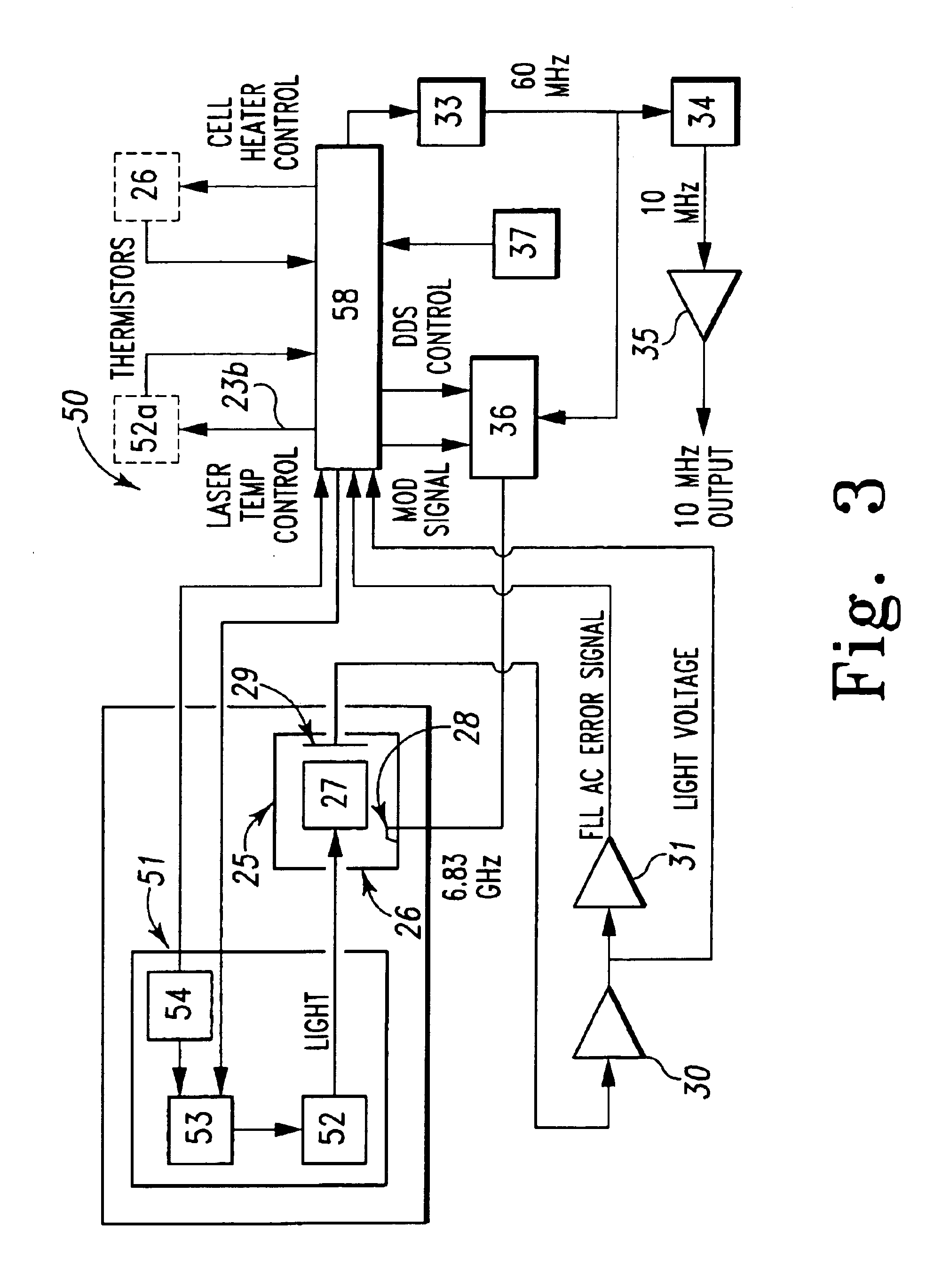
[0065]In the embodiment 50 of FIG. 3, light intensity is stabilized by controlling the means 51 for providing a controlled emission of D transition light, whether for the D1 resonance line of the atomic gas or the D2 resonance line of the atomic gas, by effecting simultaneous changes in both laser temperature and laser injection current. If only the temperature of the laser is changed in an attempt to stabilize the light intensity, the optical frequency of the laser will also be altered; likewise, if only the laser injection current is changed in an attempt to stabilize the light intensity, the optical frequency of the laser will also be altered. By themselves, neither is a permissible option since the laser light frequency must be controlled so as to make it coincide with one of the D1 or D2 optical resonance frequencies of the atoms of the atomic gas and also to control the light-shift-coefficient, kLS. In the FIG. 3 embodiment, the light intensity is controlled in such a way as n...

embodiment 60

[0069]In the embodiment 60 of FIG. 4, light intensity is stabilized by controlling the means 61 for providing a controlled emission of D transition light, whether for the D1 resonance line or the D2 resonance line of the atomic gas by variable attenuation of the D transition light emitted from the means 61. As illustrated by FIG. 4, the means 61 for controlling the emission of D transition light includes a liquid crystal light attenuator 66. Again, the intensity of the light entering cell 27 is stabilized by using essentially the same method as is used for the embodiments of FIG. 2 and FIG. 3, with the exception that the light-control element is liquid-crystal light attenuator 66 instead of devices, such as the lamp oven 23 or the laser heater 52a, that control the temperature of light sources 22 and 51, respectively.

[0070]The control output that is sent to liquid-crystal light attenuator 66 is the output of an integrator whose input is proportional to the difference between the sam...


PUM


Abstract

In an apparatus using optically excited atomic media, such as an atomic frequency standard, a source providing a controlled emission of light for exciting the D1 and / or D2 resonance lines of an alkali gas, such as rubidium or cesium, is controlled by an output generated by digital electronics from the light intensity signal of a light sensor for light transmitted by the alkali gas, an output for representing ambient temperature, and a light intensity-ambient temperature algorithm to substantially eliminate changes in light intensity due to light source aging for the purpose of reducing changes in temperature sensitivity of the apparatus as a function of time and the light-shift contribution to the frequency aging of the standard.

Description

FIELD OF THE INVENTION[0001]This invention relates to methods and apparatus using optically excitable atomic media, and, more particularly, to apparatus and methods for stabilizing atomic gas exciting light in microwave atomic frequency standards.BACKGROUND OF THE INVENTION[0002]Because modern telecommunication systems require extremely stable and accurate timing devices, atomic frequency standards have been used in such applications. For this and other applications, the overall size, operating temperature, power consumption, weight and ruggedness of the atomic standard are critical parameters.[0003]Microwave atomic frequency standards use natural resonances within atoms to keep time since the natural atomic resonances are more stable and less sensitive to environmental effects, such as temperature, pressure, humidity, vibration, acceleration, etc., than are macroscopic oscillators like pendulums and quartz crystals. The natural atomic resonances are generally ground-state microwave...

Claims


Application Information

Patent Timeline
Patent Type & Authority Patents(United States)
IPC IPC(8): G04F5/00G04F5/14G04F5/04H01S1/00H01S1/06H03L7/26H05B41/36H01S5/042H01S5/0683
CPCH01S1/06H03L7/26G04F5/145H01S5/042H01S5/0427H01S5/0683H01S5/06837H01S5/0021
Inventor DENG, JINQUANCROCKETT, JEFF D.ENGLISH, THOMAS C.
Owner MICROSEMI FREQUENCY & TIME
Why Eureka
Try Eureka