Autotiller control system for aircraft

a control system and aircraft technology, applied in the direction of instruments, navigation instruments, using reradiation, etc., can solve the problems of airline lag in achieving the effect of significant logistical and operational problems, and inability to keep up with the increasing traffic volume, etc., to maximize the precision of the host aircraft maneuvering, increase the size, and increase the effect of siz

Inactive Publication Date: 2005-08-09
THE BOEING CO
View PDF10 Cites 60 Cited by
  • Summary
  • Abstract
  • Description
  • Claims
  • Application Information

AI Technical Summary

Benefits of technology

[0040]This invention enables increased size (e.g., span and length) airplanes to operate in space constrained airport gates and taxilanes, without the disadvantages associated with prior art approaches, through use of an “autotiller” concept. The autotiller concept can be used in conjunction with the prior art approaches to yield potential additional airport compatibility advantages. The invention is intended to enable increased span configurations to be compatible with airport gate and taxilane facilities sized for smaller size and span aircraft. The invention also maximizes the precision of the host aircraft maneuvering, and therefore the realization of safety and efficiency advantages. The “autotiller” provides a method of automatically and precisely controlling nosewheel steering so as to keep the nosewheel very close to (e.g., within about plus or minus one foot of) the desired nosewheel taxiline as the aircraft taxis through “tight” taxilanes, and in and possibly out of its parking position. A precise means for sensing or computing nosewheel lateral deviation from the nosewheel taxiline are one approach to implementing the autotiller system. An example of such means uses a taxilane installed guidewire and airplane installed inductive sensors to support the autotiller steering control system. Other methods of precisely sensing/computing aircraft position/orientation to support the autotiller function include use of inertial reference equipment, ground or air based satellite or pseudo-satellite positioning systems such as GPS, optical, or radio frequency, and onground sensors such as contact, pneumatic wheel passage sensors, electroc-static, electromagnetic, radio frequency or odometry, and or any combination thereof. Modern aircraft systems frequently utilize sensors from a plurality of suitable choices depending on costs, availability, and redundancy requirements. Lateral position sensing/computing can be combined with longitudinal position sensing/computing, and the automatic nosewheel steering can optionally be combined with automatic thrust and automati

Problems solved by technology

However, airport support infrastructure, has not kept pace with increasing traffic volume, and is expected to lag further in the coming decades.
Airlines experience significant logistical and operational problems trying to physically accommodate the increased wingspan, that which characterizes the new stretch derivative and super jumbo aircraft, in airport gates and taxiways designed for smaller aircraft.
The increased wingspan and/or length of larger aircraft will make parking such aircraft next to each other at gates more risky in terms of probability of collision, and will also increase problems related to ground services, arrangements, flows, and congestion.
Similarly, the increased wingspan increases the probability of collisions between aircraft taxiing on adjacent taxiways/taxilanes or fixed objects.
This is a reasonable approach, but is inherently limited in the amount of additional passenger volume it can develop.
Airline fleet mix, and more particularly the fleet mix present at each hub complex (i.e., the mix of aircraft actually present simultaneously at a gate constrained hub airport), can reduce the effectiveness of this strategy in increasing passenger volume.
The FAA does not regulate actual clearances used by airlines in their day-to-day commercial operations.
An obvious disadvantage of this second approach is that it increases the probability of collisions, and requires increased pilot attention and precision for the taxiing and parking tasks.
While this approach increases the size of the largest accommodatable aircraft, it

Method used


Image

  • Autotiller control system for aircraft
  • Autotiller control system for aircraft
  • Autotiller control system for aircraft

Examples


Embodiment Construction

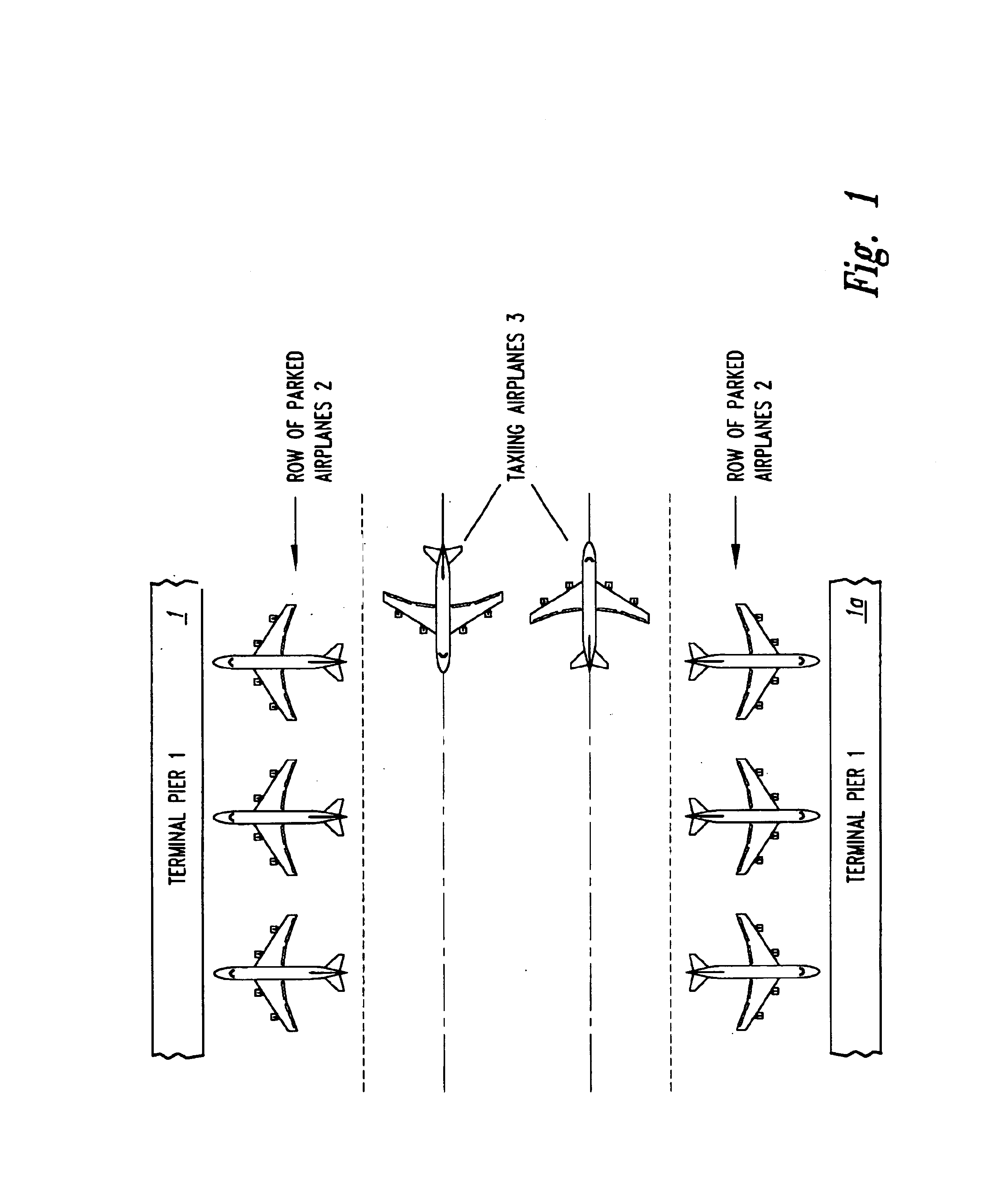
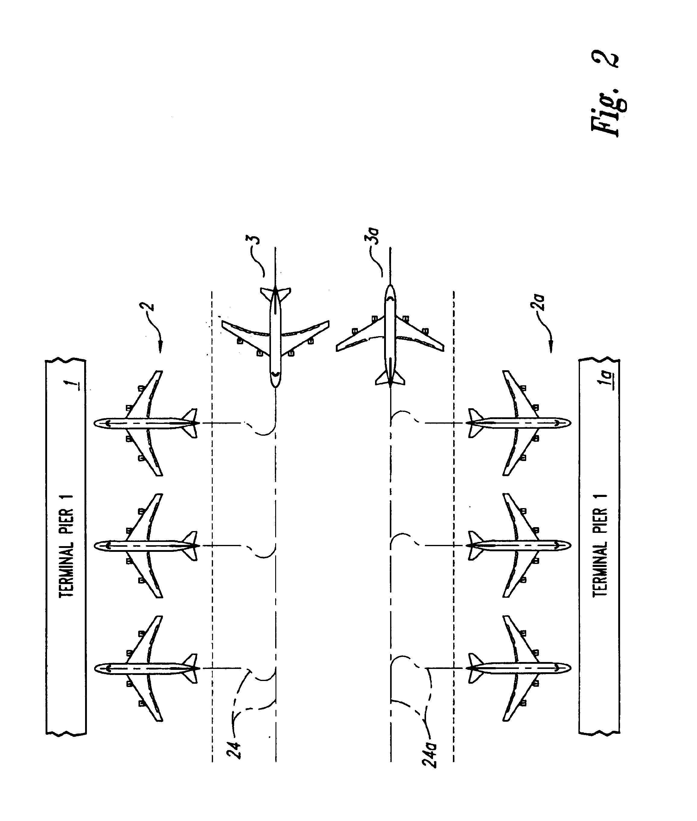
[0062]FIGS. 1 and 2 illustrate application of the autotiller concept to a representative airport situation. FIG. 1 shows a typical airport situation, with two terminal piers 1 flanking a paved area accommodating two rows of parked airplanes 2 and dual taxilanes for permitting two taxiing airplanes 3 to pass each other without having to stop or swerve to avoid risking wingtip collision. Typical operational separations are nose-to-terminal face clearance of 20′, moving wingtip-to-parked airplane tail clearance of 30′, moving wingtip-to-moving wingtip clearance of 35′, and parked wingtip-to-parked wingtip clearance of 25′. Depending on the airport, airplane size, class, and airline particulars, these clearance criteria are varied somewhat.

[0063]FIG. 2 shows a similar airport scenario, with larger autotiller equipped parked airplanes 2A and taxiing airplanes 3A in the same facilities designed for smaller non-autotiller equipped airplanes. The above-mentioned clearances can now be reduce...


PUM


Abstract

An automatic guidance and control system for aircraft moving on the ground. On-ground taxi control is provided in response to steering commands for nosewheel positioning.

Description

FIELD OF THE INVENTION[0001]This invention pertains to automatic guidance and control systems for aircraft moving on the ground.BACKGROUND OF THE INVENTION[0002]Deregulation of the airline industry has resulted in reduced airfares, which when combined with stable fuel prices, has further produced a volume of air travel that has been strongly and steadily increasing in the past decade. This trend is expected to continue unabated over the next two decades. However, airport support infrastructure, has not kept pace with increasing traffic volume, and is expected to lag further in the coming decades. Due to the limited numbers of airport gates, there is a strong motivation for airlines to move to larger aircraft to accommodate increased passenger volume through fewer gates. The need for larger aircraft is particularly critical at major “hub” airports in the “hub and spoke” systems operated by most large airlines in order to maximize passenger flow through their limited airport facilitie...

Claims


Application Information

Patent Timeline
IPC IPC(8): B64C25/00B64F1/22B64C25/50B64F1/00G01C21/00G06F19/00G08G5/06
CPCB64C25/50B64F1/002G08G5/0021G08G5/065
Inventor SANKRITHI, MITHRA M. K. V.
Owner THE BOEING CO
Why Eureka
Try Eureka