
Interactive repeater insertion simulator (IRIS) system and method

a repeater and simulator technology, applied in the field of integrated circuit design, can solve the problems of degrading the signal, affecting the design, and often displaying larger global signals than desirable propagation delays, so as to achieve quick and easy optimization of the design

Inactive Publication Date: 2005-08-09
HEWLETT PACKARD DEV CO LP
View PDF17 Cites 13 Cited by
  • Summary
  • Abstract
  • Description
  • Claims
  • Application Information

AI Technical Summary

Benefits of technology

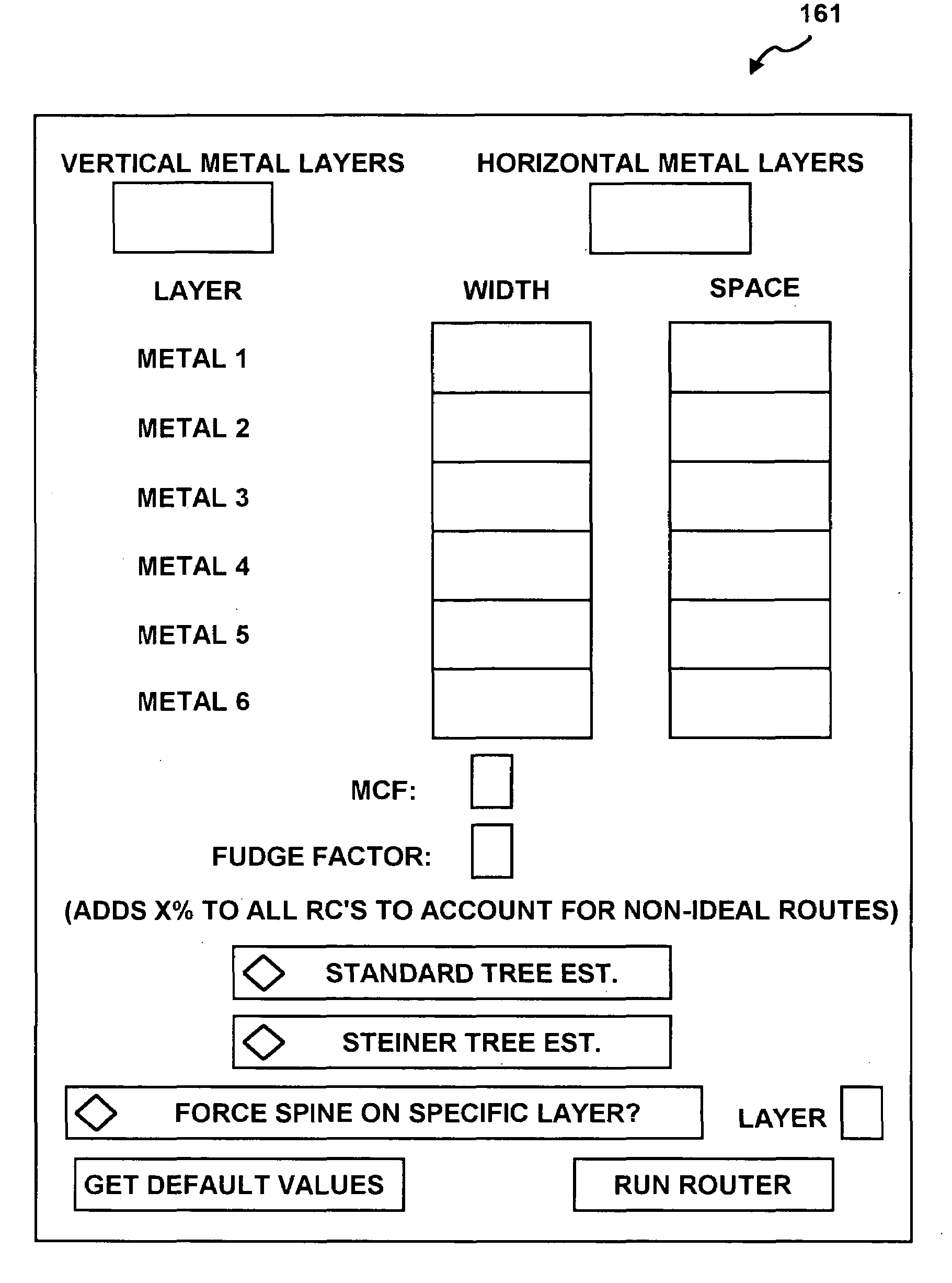
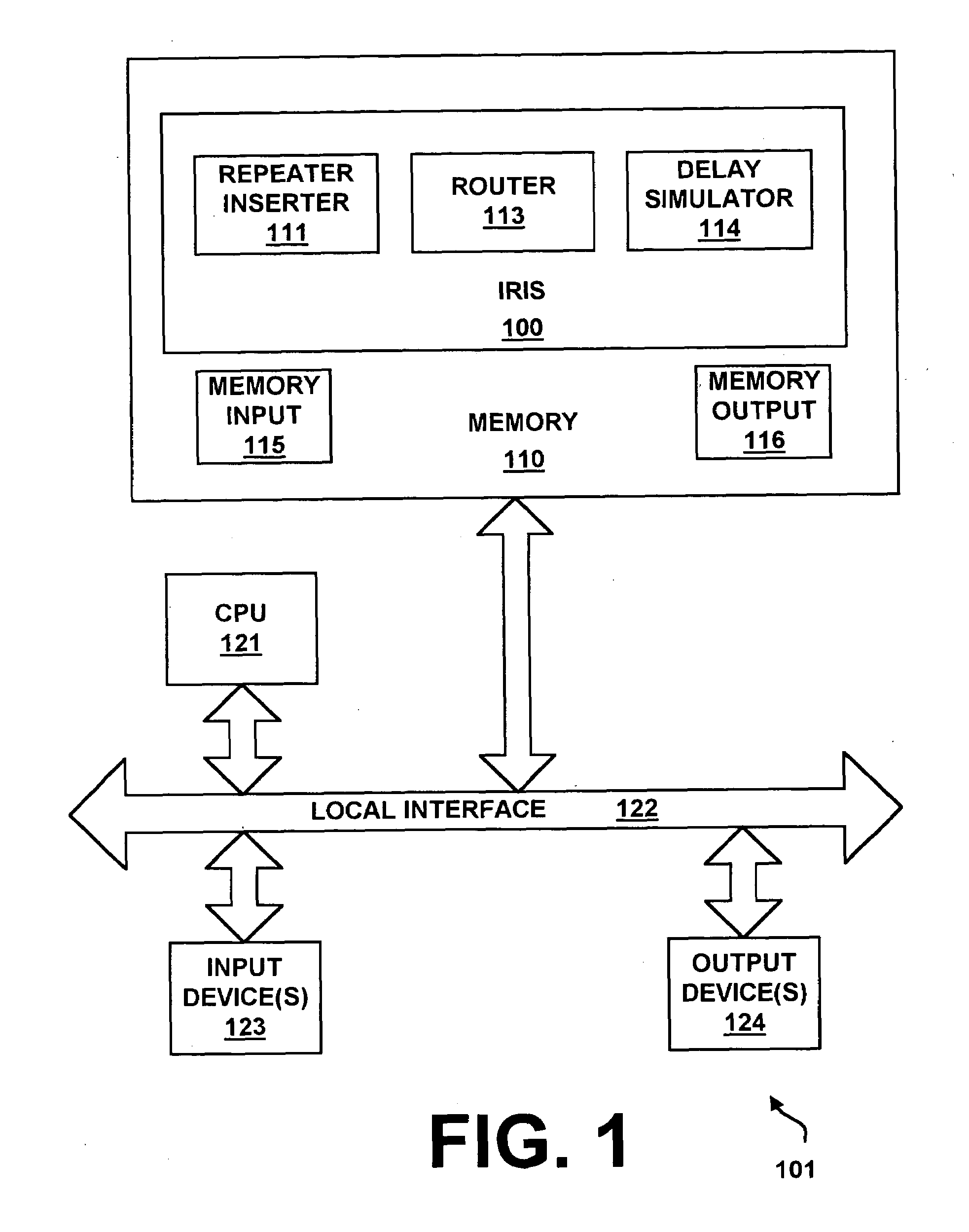
[0008]Briefly described, the invention provides a interactive repeater insertion simulator (IRIS) system and method for quickly and easily optimizing the design of an IC interconnect for an electrical signal through the insertion of repeaters (buffers or drivers).
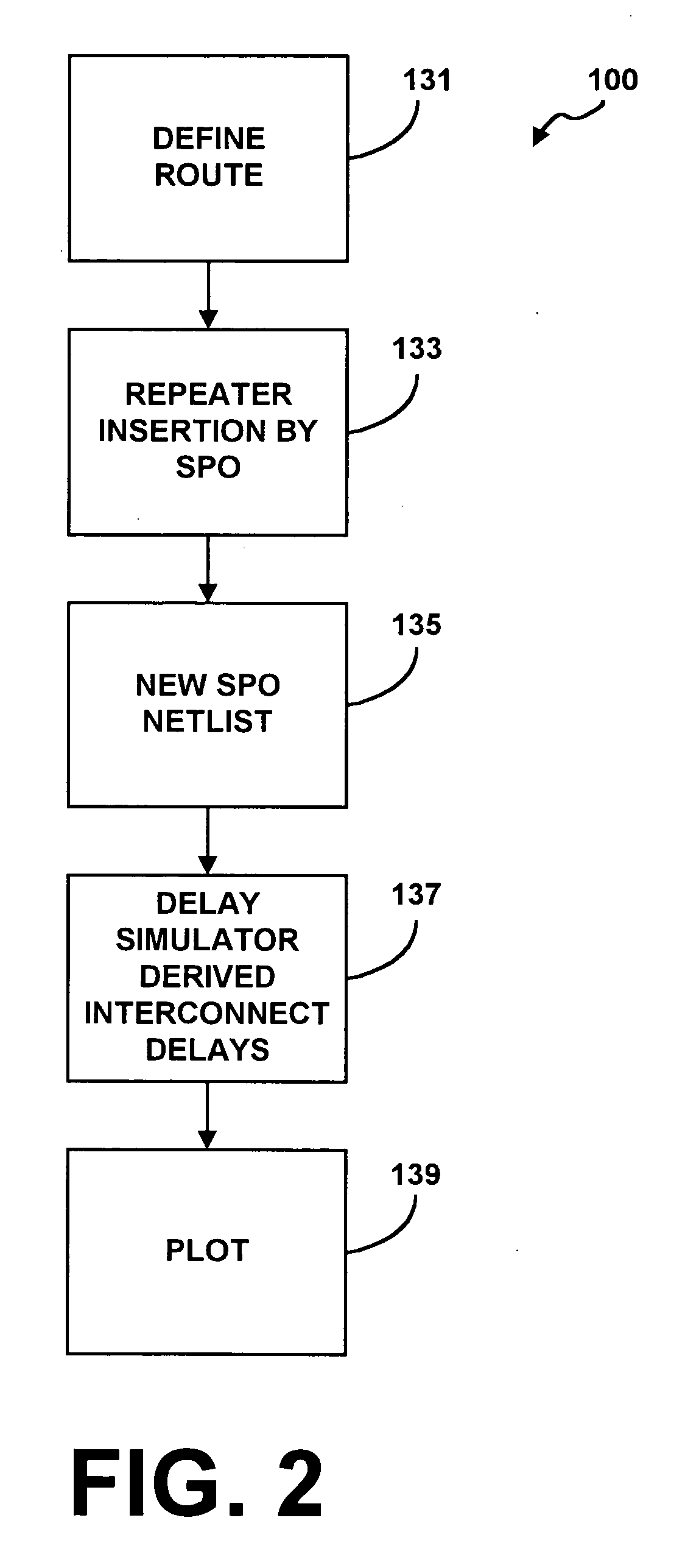
[0009]Generally, in architecture, the IRIS system utilizes the combination of a router, a simultaneous path optimizer, and a delay simulator to efficiently simulate repeater insertion. The router defines the route between more than one circuit and derives a first netlist. The first netlist is then sent to a repeater inserter, which, in accordance with the preferred embodiment of the invention, is a simultaneous path optimization (SPO) system, to define the insertion of repeaters. A second netlist is outputted from the SPO system having thereupon one or more repeaters, inserted, and the physical locations of these repeaters along the interconnect for optimal performance, and minimum propagation delay. The delay simulator is then run on the second netlist to calculate the new interconnect delays. The interconnect delays may be plotted, if desired, thereby displaying a representation of the interconnect delays.

Problems solved by technology

The problem is compounded even further as IC chips get larger and larger.
Therefore, global signals often exhibit larger than desirable propagation delays, and the circuits which provide these signals need to be optimized so that signals may meet timing specifications.
Generally, the propagation delay associated with a signal, or the time necessary for the signal to propagate from one point to another on a chip, is caused by resistances and / or capacitances imposed upon the signal path, and is sometimes referred to as “RC delay.” These resistances and capacitances also degrade the signal (decrease its rising / falling slope) as the signal propagates along a connection, which is another undesirable deleterious effect.
However, this process is time consuming and has traditionally been performed by having an engineer or designer review circuit models and determine where to insert repeaters.
Although the foregoing software programs can be used for modeling and simulations, they do not automatically determine where and to what extent repeaters should be placed within a circuit, nor do they allow a user to specify interconnect specifications in conjunction with repeater insertion and to see the effects on propagation delay caused by such insertion.
Thus, a heretofore unaddressed need exists in the industry for a way to automatically and efficiently determine the most efficient positioning of repeaters when designing an IC in order to reduce signal propagation delays in the IC.

Method used


Image

  • Interactive repeater insertion simulator (IRIS) system and method
  • Interactive repeater insertion simulator (IRIS) system and method
  • Interactive repeater insertion simulator (IRIS) system and method

Examples


Embodiment Construction

[0026]The interactive repeater insertion simulator (IRIS) system 100 of the present invention can be implemented in software, firmware, hardware, or a combination thereof. In the preferred embodiment of the invention, which is intended to be a nonlimiting example, the IRIS system 100 is implemented in software that is executed by a computer, for example, but not limited to, a personal computer, workstation, minicomputer, or mainframe computer.

[0027]The software-based IRIS system 100, which comprises an ordered listing of executable instructions for implementing logical functions, can be embodied in any computer-readable medium for use by or in connection with an instruction execution system, apparatus, or device, such as a computer-based system, processor-containing system, or other system that can fetch the instructions from the instruction execution system, apparatus, or device and execute the instructions. In the context of this document, a “computer-readable medium” can be any m...


PUM


Abstract

An interactive repeater insertion simulator (IRIS) system and method quickly and easily optimize the design of an integrated circuit (IC) interconnect for an electrical signal through the insertion of repeaters. The IRIS system utilizes the combination of a router, a repeater inserter, and a delay simulator to efficiently simulate repeater insertion. The router defines the route between more than one circuit and derives a first netlist. The first netlist is then sent to the repeater inserter to define the insertion of repeaters. A second netlist is outputted from the repeater inserter having thereupon one or more repeaters, inserted, and the physical locations of these repeaters along the interconnect for optimal performance, and minimum propagation delay. The delay simulator is then run on the second netlist to calculate the new interconnect delays. The interconnect delays may then be plotted or otherwise output for examination.

Description

FIELD OF THE INVENTION[0001]The present invention generally relates to integrated circuit design, and more particularly, to an interactive repeater insertion simulator (IRIS) system and method for allowing a user to quickly and easily optimize the design of an integrated circuit (IC) interconnect for an electrical signal through the insertion of repeaters (buffers or drivers).BACKGROUND OF THE INVENTION[0002]As operating frequencies increase to hundreds of megahertz (MHz) for multimedia processors and application specific integrated circuits (ASICs), and increase to around a gigahertz (GHz) for the next generation of central processing units (CPUs), global electrical signals, for example, reset, stall, clock, and control, have less time to traverse an integrated circuit (IC) on a microchip (chip) due to reduced cycle time. The problem is compounded even further as IC chips get larger and larger. Therefore, global signals often exhibit larger than desirable propagation delays, and th...

Claims


Application Information

Patent Timeline
Patent Type & Authority Patents(United States)
IPC IPC(8): G06F9/45G06F17/50
CPCG06F17/5009G06F17/505G06F2217/84G06F30/327G06F2119/12G06F30/20
Inventor WANEK, JOHN D
Owner HEWLETT PACKARD DEV CO LP
Learn More