Rotary cutting tool

a cutting tool and rotary technology, applied in the direction of turning drills, manufacturing tools, wood boring tools, etc., can solve the problem of the nose that forms a portion of each cutting edge breaking away, and achieve the effects of high chip forming productivity, high mechanical stability, and good surface quality

Inactive Publication Date: 2005-08-16
KENNAMETAL INC
View PDF34 Cites 51 Cited by
  • Summary
  • Abstract
  • Description
  • Claims
  • Application Information

AI Technical Summary

Benefits of technology

[0005]The object of the invention is to provide a rotary cutting tool that is particularly mechanically stable, particularly a drill, said too

Problems solved by technology

During drilling, however, there arises the danger of a nos

Method used


Image

  • Rotary cutting tool
  • Rotary cutting tool
  • Rotary cutting tool

Examples


Embodiment Construction

[0037]In all figures corresponding components are identified with the same reference designations.

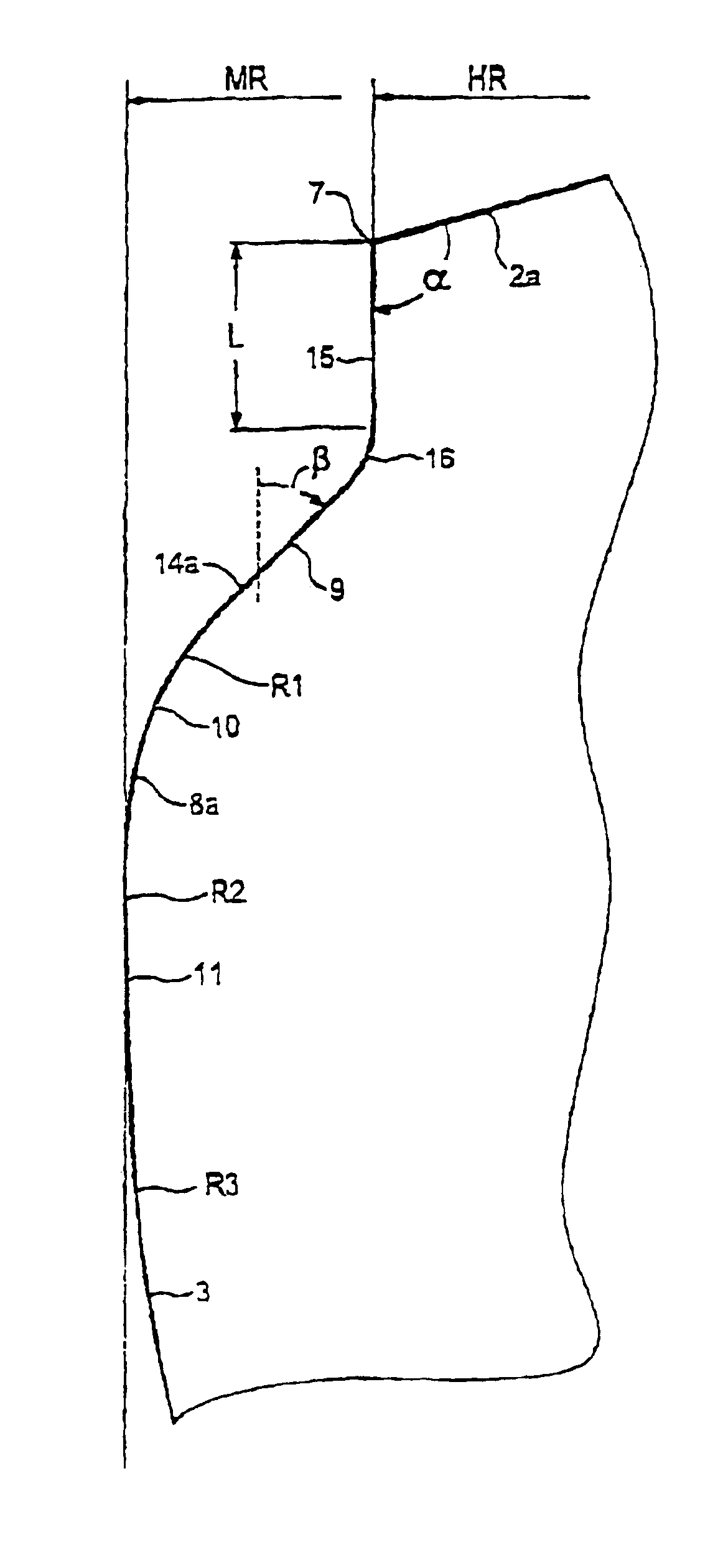
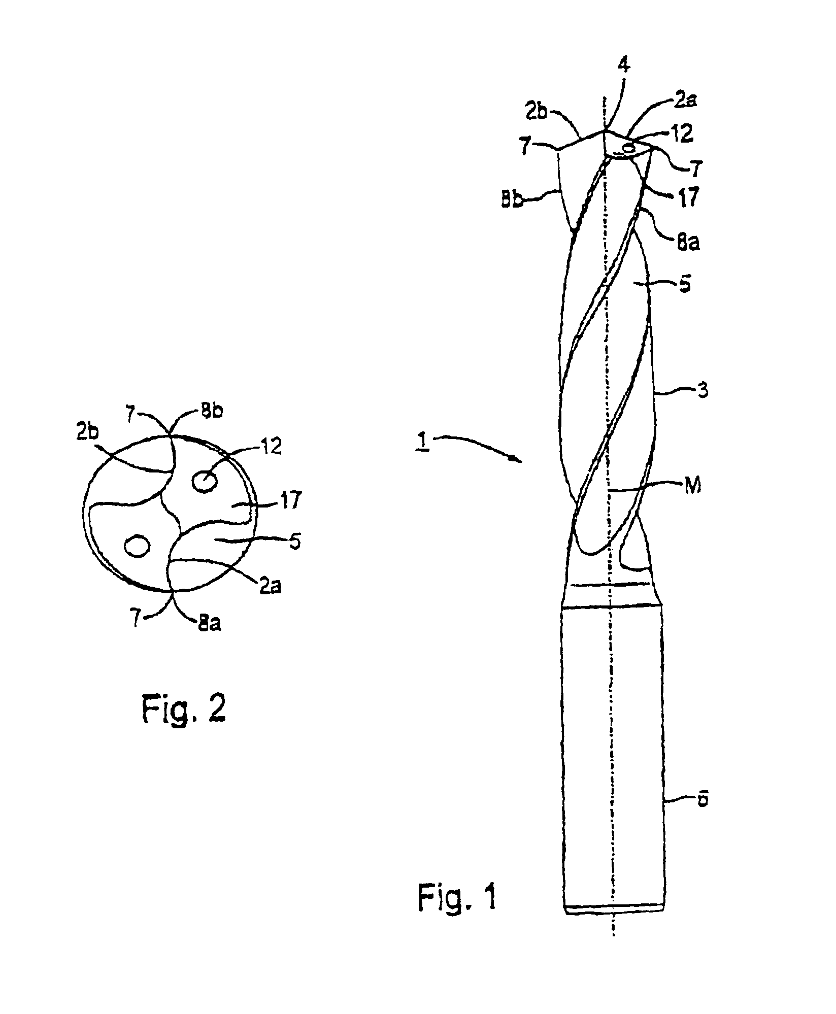
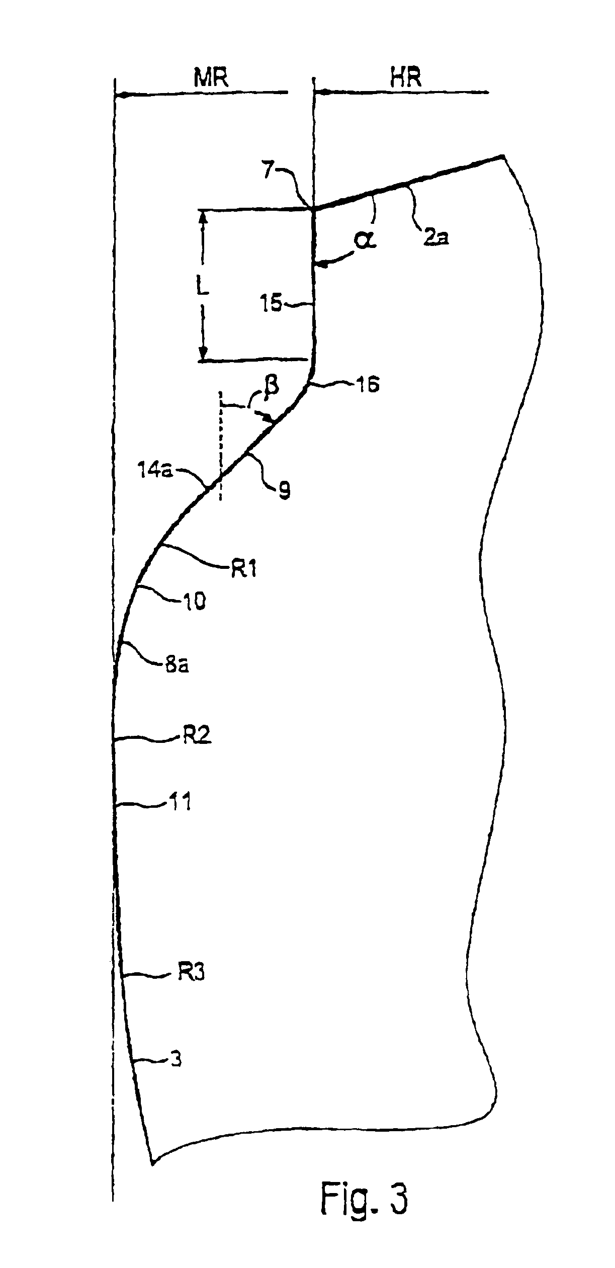
[0038]FIGS. 1 to 3 show a rotary tool configured as drill 1, generally referred to as rotary cutting tool, that has two main cutting edges 2a,2b that are arranged symmetrically with respect to the central axis M of a cutter portion 3. The main cutting edges 2a,2b are produced by grinding from the material of the cutter portion 3 and abut with one another at the tip 4 of the drill 1 with an obtuse angle. Two flute grooves 5 extend helically in the manner of a screw threading from the tip 4 to a clamping end or retaining portion 6 of drill 1. An embodiment with a greater number of main cutting edges can also be realized.

[0039]In the embodiment according to FIG. 1, the main cutting edges 2a,2b are arranged symmetrically with respect to the central axis M of the cutter portion 3 and of the drill 1. Particularly in the case of a greater number of main cutting edges, such can be arranged to b...


PUM

PropertyMeasurementUnit
Fractionaaaaaaaaaa
Fractionaaaaaaaaaa
Angleaaaaaaaaaa

Abstract

There is now provided a rotary cutting tool, particularly a drill, that has at least two cutting edges that respectively comprise a main cutting edge and that respectively are disposed, particularly symmetrically, with respect to the central axis of a cutter portion, whereby the radius of the main cutting edges is less than the maximal cutting edge radius of the cutter portion. A secondary cutting edge is associated with a main cutting edge, this secondary cutting edge is curvilinear in at least a portion and is configured as smooth finishing cutting edge, this secondary cutting edge comprises a plurality of curve-forming radii, whereby in an outer smooth finishing region within the region of the maximal cutting edge radius, the curve-forming radius of the smooth finishing cutting edge is greater than the maximal cutting edge radius. The cutter portion that is adjacent to the outer smooth finishing region is tapered by a taper that diminishes the size in the direction away from the main cutting edges.

Description

BACKGROUND OF THE INVENTION[0001]1. Field of the Invention[0002]This invention relates to a rotary cutting tool, for example, a drill, such as, for example, a twist drill, a wiper twist drill, a drill with straight flutes, a countersink tool, or a reaming tool, that has at least two cutting edges, said cutting edges respectively comprising a main cutting edge, and said cutting edges being disposed, particularly symmetrically, with respect to the central axis of a cutter portion.[0003]2. Background Information[0004]Such a rotary cutting tool that is configured as a drill is known, for example, from International Patent Publication No. WO 01 / 76794 A1. That drill comprises a plurality of cutting edges that are produced either by grinding of the tip structure of the drill per se, or the cutting edges are portions of a cutting insert. The cutting edges are limited by so-called noses that are disposed at the outer edges of the cutting edges, said noses having several radii of curvature. B...

Claims


Application Information

Patent Timeline
IPC IPC(8): B23B51/02B23B51/00
CPCB23B51/00B23B51/02B23B2222/16B23B2222/28B23B2226/125Y10T408/455B23B2226/315B23B2251/14Y10T408/909Y10T408/9097Y10T408/906B23B2226/18
Inventor PROKOP, HERMANN F.
Owner KENNAMETAL INC
Why Eureka
Try Eureka