Mandrel-assisted resin transfer molding process employing resin outflow perimeter channel between male and female mold elements

a technology of resin transfer molding and mandrel, which is applied in the direction of butter manufacturing, turning machine accessories, drawing profiling tools, etc., can solve the problems of poor part yield, less robust materials, and high cost of very robust molds used in rtm processes, so as to increase the density of parts, easy to excavate from parts, and increase the resin outflow

Inactive Publication Date: 2005-08-16
CALDWELL DESIGN & FABTION
View PDF3 Cites 25 Cited by
  • Summary
  • Abstract
  • Description
  • Claims
  • Application Information

AI Technical Summary

Benefits of technology

[0012]These indexing elements vertically locate the male mold element relative to the top surface of the female mold element, placing the male mold element into the female mold element at a depth that precisely defines the geometry parameters of the mold cavity. Once inserted, the male mold element may be retained in its intended mold cavity-forming position by means of clamps and the like at the various indexing elements. As an auxiliary measure, the upper portion of the mold assembly may be engaged by a mandrel coupled to a vacuum. The vacuum closure augments the outflow of resin and removal of air pockets from the mold cavity through the annular channel, as the male mold element is compressed against the resin-impregnated preform.
[0013]As resin is drawn out from the mold cavity, it enters the channel, forming a thin band of resin that is contiguous with the resin in the mold cavity. This thin band creates resin weight around the edge of the mold to assist in forcing air out of the mold cavity and increasing part density. Once the resin has cured, and the mold halves removed, the thin resin band is readily excised from the part, leaving the article completely finished on both sides, as desired.

Problems solved by technology

However, because of the relatively low volume per part, these enterprises cannot afford the very substantial cost of very robust (typically steel) molds used in RTM processes employed in the automotive and aircraft industries.
Instead, the RTM systems that have been used for low margin, limited part production, such as in the marine manufacturing industry, are typically made from less robust materials, such as epoxy resins, which suffer from poor part yield and are prone to frequent failures.
Each repetition of the resin bleeding and inspection step is time consuming, primarily due to the fact that, after the operator bleeds resin into the collection reservoir, the pressure tank must be pressurized again.
Typically, this bleeding and inspection step is repeated at least three or four times for each molded article, making the resin transfer molding process a relatively lengthy and expensive task.
Resin is also wasted each time the operator is required to bleed the resin into the collection reservoir to inspect it for air bubbles.
Because this occurs several times during the molding of each article, the volume of wasted resin and associated cost can be substantial.
Another drawback of such a conventional molding process is the fact that it relies upon operator judgment to hopefully correctly determine (based upon what the operator perceives is a lack of air bubbles in the resin bled into the collection reservoir) if and when the mold cavity and fiber preform have been completely filled with resin.
Even if the operator accurately observes no air bubbles in resin that has been bled into the collection reservoir, this is no assurance that the mold cavity is free of voids.
This inability of the operator to ensure that the mold is void-free results in poor repeatability, and lower overall quality and yield of the articles being produced.
In addition, irrespective of the skill and experience of the operator, the architecture and manner of assembly of the two mold halve themselves can result in a less than satisfactory product.
As this can cause bunching together or even pulling of the fibers of the preform, it leads to inconsistencies in the thickness and density of the preform material at the joined mold edges and also within the mold cavity.
This not only causes variations in the dimensions of the molded article, but can create variations in the flow of resin through the mold cavity, leading to air pockets, that are not discovered until the part has been cured and removed from the mold.

Method used


Image

  • Mandrel-assisted resin transfer molding process employing resin outflow perimeter channel between male and female mold elements
  • Mandrel-assisted resin transfer molding process employing resin outflow perimeter channel between male and female mold elements
  • Mandrel-assisted resin transfer molding process employing resin outflow perimeter channel between male and female mold elements

Examples


Embodiment Construction

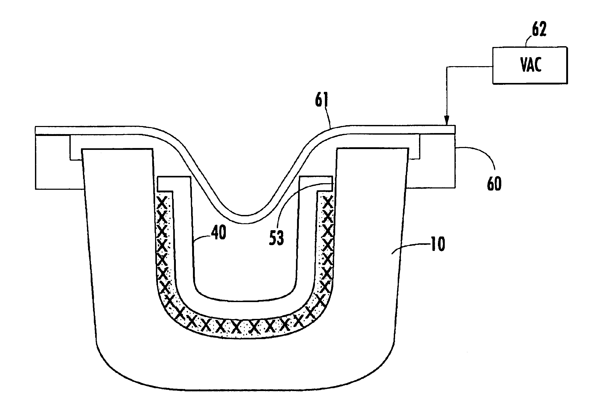
[0017]Before describing in detail the new and improved mandrel-assisted resin transfer molding method and apparatus therefor in accordance with the present invention, it should be observed that the invention resides primarily in a prescribed geometric relationship between mutually adjacent sidewall surfaces of each of the interior male mold element and the outer female mold element. As a consequence, the configurations of the components of the mandrel-assisted resin transfer molding architecture of the invention and the manner in which they are positioned relative to one another have, for the most part, been illustrated in the drawings in a readily understandable diagrammatic pictorial format, which shows only those specific details that are pertinent to the present invention, so as not to obscure the disclosure with details which will be readily apparent to those skilled in the art having the benefit of the description herein.

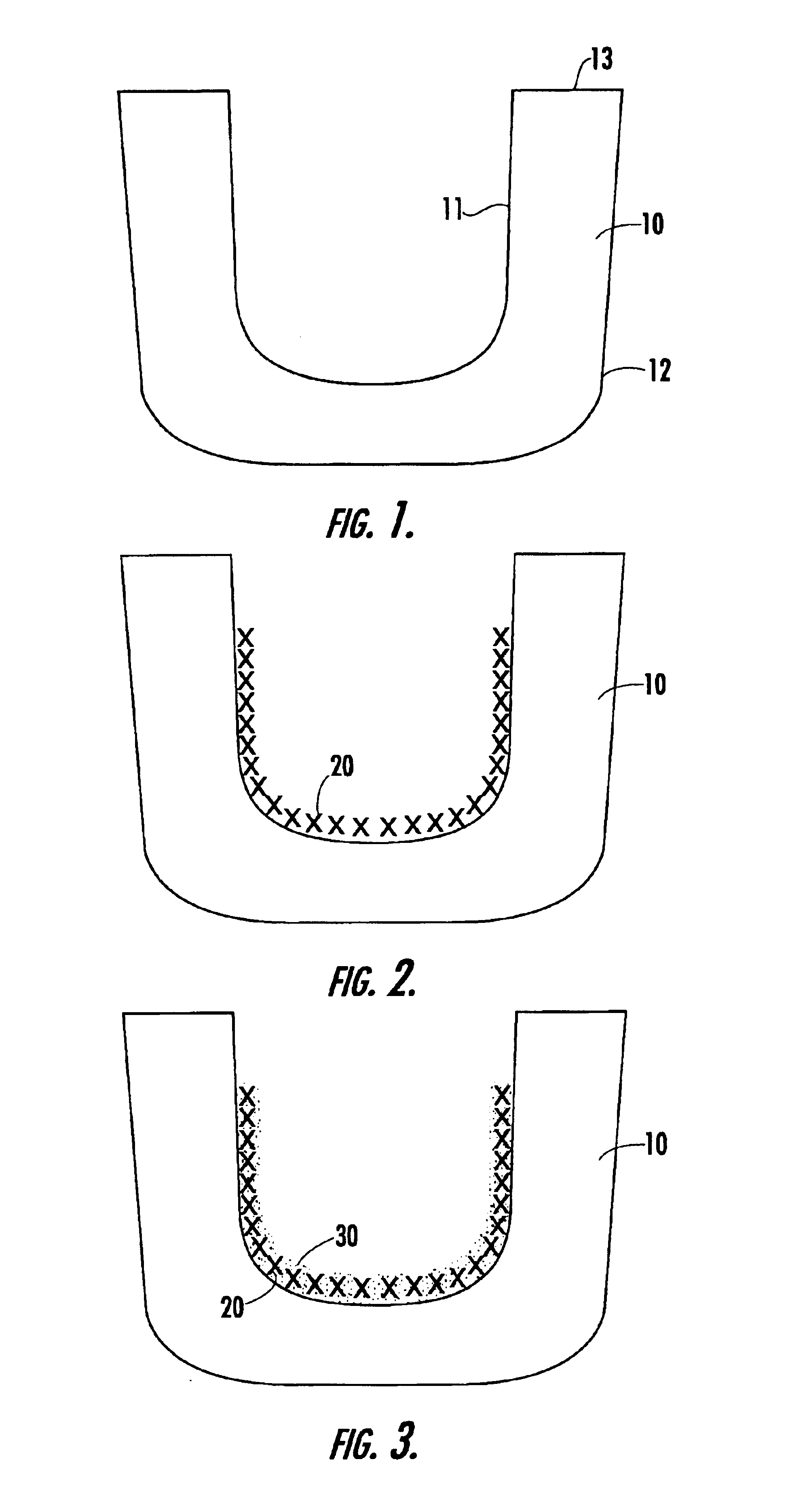
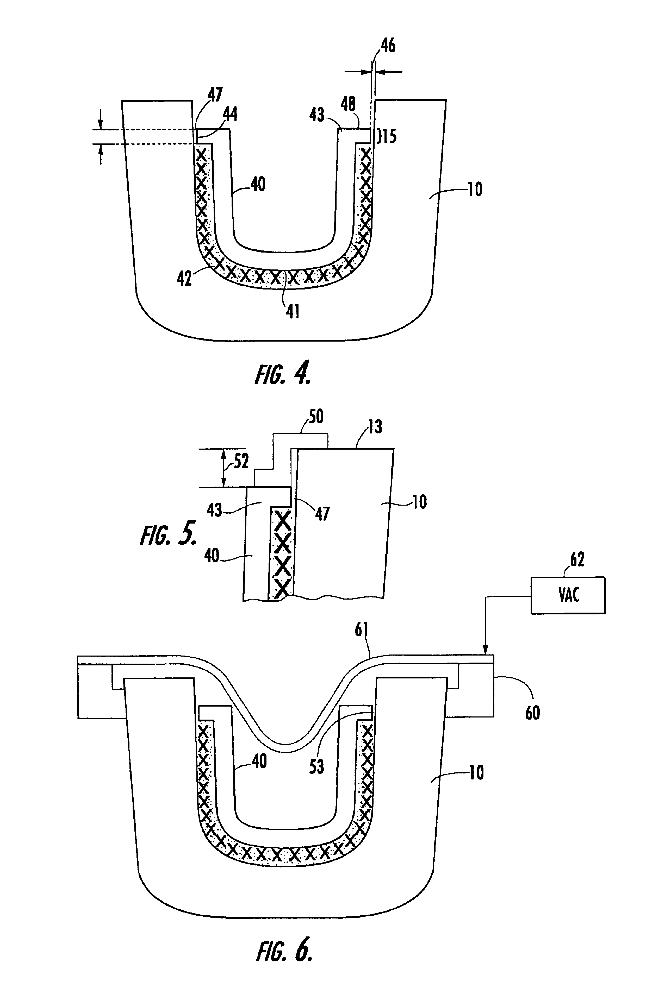
[0018]Attention is now directed to FIGS. 1-8, which are ...


PUM

PropertyMeasurementUnit
volumeaaaaaaaaaa
perimeteraaaaaaaaaa
geometric shapeaaaaaaaaaa

Abstract

A mandrel-assisted resin transfer molding process and apparatus therefor provides a generally continuous, narrow annular channel between the perimeter of an inner male mold element and an outer female mold element. This channel allows air, heat and vapor to evenly escape and resin to outflow from the mold cavity everywhere around the edge of the part being molded. A very thin resin band forms in the channel is easily trimmed away, leaving the article completely finished on both sides and having a well defined edge that does not require shaping.

Description

CROSS-REFERENCE TO RELATED APPLICATIONS[0001]The present application is a continuation of U.S. patent application Ser. No. 09 / 828,293, filed Apr. 6, 2001, now abandoned, by J. Caldwell, Jr., entitled: “Mandrel-Assisted Resin Transfer Molding Process Employing Resin Outflow Perimeter Channel Between Male And Female Mold Elements”, and is assigned to the assignee of the present application and the disclosure of which is incorporated herein.FIELD OF THE INVENTION[0002]The present invention relates in general to resin transfer molding (RTM) process and apparatus therefor, and is particularly directed to a new and improved RTM architecture that employs a generally continuous and relatively narrow, annular channel between the perimeter of an inner male mold element and an outer female mold element. This perimeter channel allows resin and air to readily escape everywhere around the edge of the part being molded, resulting in the molded part having a well defined edge of resin material, so ...

Claims


Application Information

Patent Timeline
Patent Type & Authority Patents(United States)
IPC IPC(8): B29C70/04B29C70/48
CPCB29C70/48Y10S425/812
Inventor CALDWELL, JR., JAMES D.
Owner CALDWELL DESIGN & FABTION
Why Eureka
Try Eureka