Capacitive probe assembly with flex circuit

a probe assembly and flex circuit technology, applied in the direction of resistance/reactance/impedence, measurement devices, instruments, etc., can solve the problem of not being able to compete with the spacing of the integrated circuit package test, and achieve the effect of reducing the complexity of the tester control circuitry, reducing the number of probe assemblies, and reducing the in-circuit test tim

Inactive Publication Date: 2005-08-16
AGILENT TECH INC
View PDF8 Cites 66 Cited by
  • Summary
  • Abstract
  • Description
  • Claims
  • Application Information

AI Technical Summary

Benefits of technology

[0013]This invention is advantageous over the prior art for several reasons. First, the use of a flex circuit allows multiple signal wires between the capacitive probe assembly and testing circuit allows the ability to provide multiple capacitive sensors on a single capacitive probe assembly, which in turn reduces the complexity of the tester control circuitry (e.g., robotics), reduces the number of probe assemblies required to test a given circuit under test, and reduces in-circuit test time (since fewer capacitive sensors need be shared).
[0014]In addition, since the number of connecting wires between the capacitive probe assembly and testing circuit are not limited to only a single pair as in the prior art, the use of a flex circuit allows the ability to separate the power and signal channels of each capacitive sensor on the assembly. This allows higher-precision measurements and less-sensitive communication circuitry.
[0015]Furthermore, the use of a flex circuit allows the ability to collect measurements from each of the capacitive sensors in parallel, which significantly reduces test time.

Problems solved by technology

Although the size of a capacitive probe assembly may be made to be quite small, it cannot compete with the spacing of integrated circuit package test leads.

Method used


Image

  • Capacitive probe assembly with flex circuit
  • Capacitive probe assembly with flex circuit
  • Capacitive probe assembly with flex circuit

Examples


first embodiment

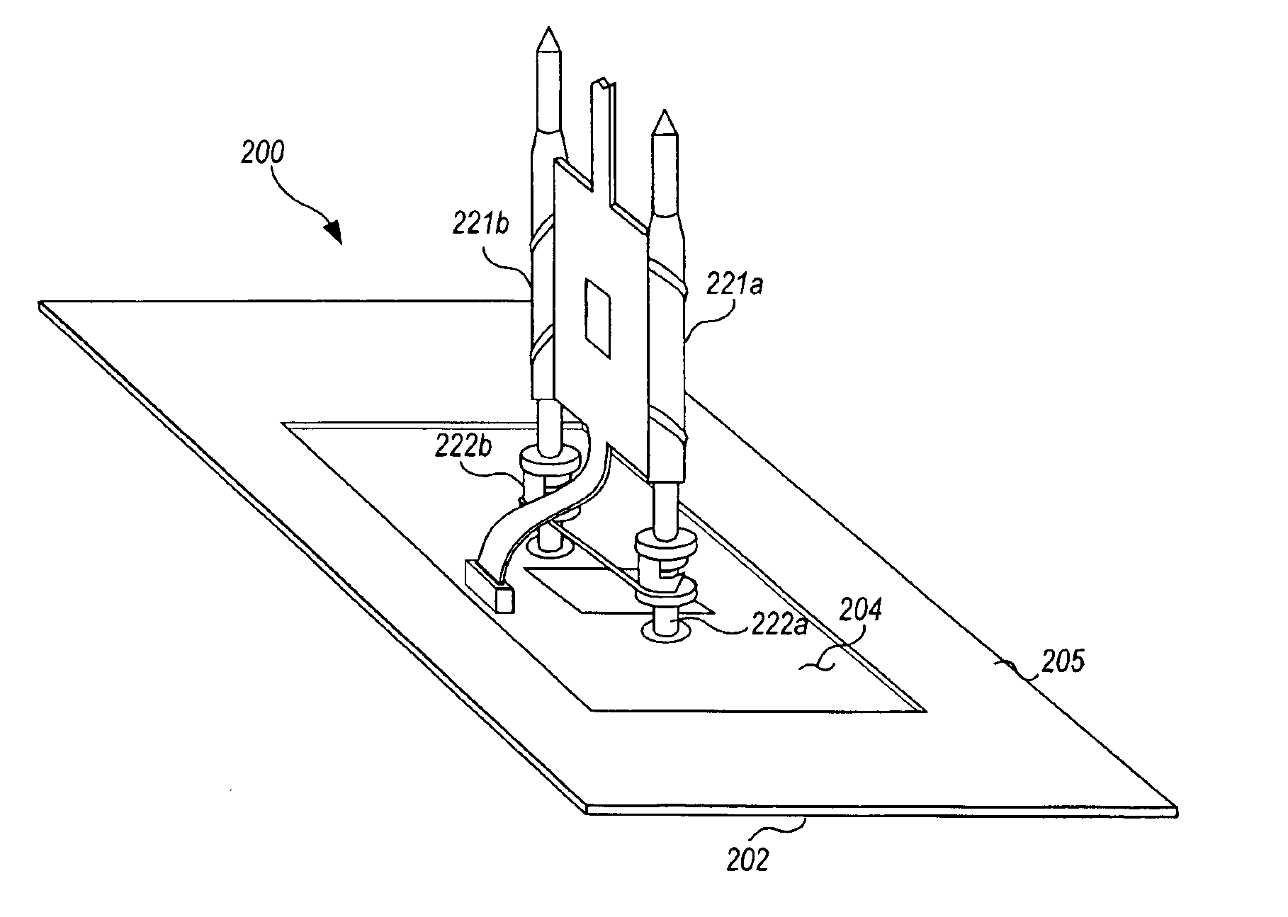
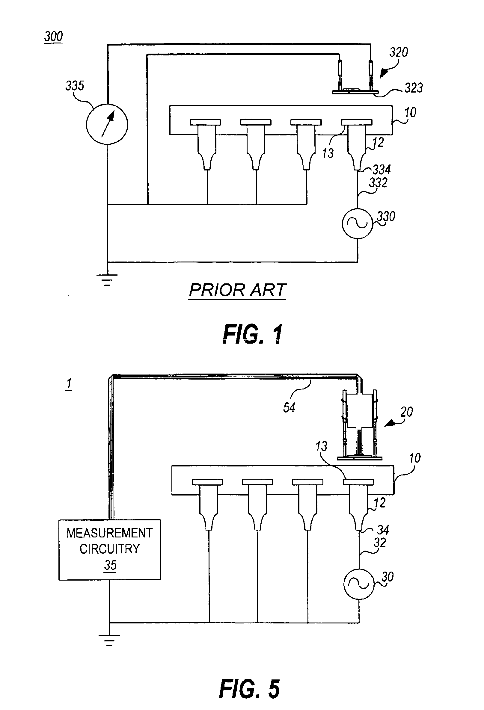
[0036]Turning now to the invention, FIG. 5 illustrates an open-fault circuit test system 1 which utilizes a capacitive probe assembly 20 implemented in accordance with the invention. As shown, the open-fault circuit system 1 includes a signal source 30 with an output connected to a printed circuit board trace 32 that is designed to connect to integrated circuit lead 12 under test at 34.

[0037]A capacitive probe assembly 20 implemented in accordance with the invention is placed on top of the integrated circuit package 10. A thin dielectric (not shown) may be placed between the component package 10 and the test probe 20. The capacitive probe assembly 20 is connected to measurement circuitry 35 which may include an ammeter, a voltmeter or computing means to compute the effective capacitance. When a given measurement falls outside predetermined limits, the connection between the lead 12 under test and the trace 32 is diagnosed as being open.

[0038]When the test is performed, the signal so...

exemplary embodiment 200

[0052]FIG. 12 is a schematic of an exemplary embodiment 200 of the active buffer circuit 60a used in accordance with the present invention. Referring now to FIG. 12, the buffer circuit 200 is a standard amplifier circuit used to amplify the signal received from the capacitive plate 23, thus increasing the signal to noise ratio and decreasing the effects of stray capacitance. There can be many alternative circuits to accomplish this amplifying effect as would be readily apparent by an artisan in the field. The amplifier 200 includes a standard operational amplifier 204, standard silicon small signal diodes 205 and 206, and a standard 7.5 V zener diode 211. Resistors 207 and 208 are 100 K ohm resistors and resistors 209 and 210 are 1 M ohm and 464 ohm resistors, respectively. The circuit input 203 is electrically coupled to the trace connected to signal probe 29a to receive the capacitvely coupled signal from the capacitive plate 23. The circuit output 201 is electrically coupled to t...


PUM


Abstract

A novel capacitive sensor assembly that utilizes a flex circuit for amplification of capacitively sensed signals and for separating the power, ground, and measurement signals is presented. The use of a flex circuit in the capacitive probe assembly allows implementation of multiple capacitive sensors for respectively capacitively coupling multiple signals from respective multiple test points of a circuit under test. The invention integrates the sensor plate, amplifier, and return wiring for each capacitive sensor all onto one flex circuit.

Description

BACKGROUND OF THE INVENTION[0001]The present invention pertains generally to electrical circuit testing and more particularly to a capacitive probe assembly with flex circuit for use in printed circuit board testing.[0002]Capacitive coupling sensors are used in the testing of electrical circuits for the identification of open-circuit faults. These sensors are regularly used to determine whether the leads of semiconductor components are present and properly soldered or otherwise connected to a printed circuit board. Typical implementation of capacitive probe assemblies that implement a capacitive sensor may be found in the following references, each of which is incorporated herein by reference for all that it teaches: U.S. Pat. No. 5,498,964, to Kerschner et al., entitled “Capacitive Electrode System for Detecting Open Solder Joints in Printed Circuit Assemblies”, U.S. Pat. No. 5,124,660 to Crook et al., entitled “Identification of Pin-Open Faults By Capacitive Coupling Through the I...

Claims


Application Information

Patent Timeline
Patent Type & Authority Patents(United States)
IPC IPC(8): G01R27/26G01R31/04G01R31/312
CPCG01R31/312G01R31/70
Inventor TESDAHL, CURTIS A.CROOK, DAVID T.
Owner AGILENT TECH INC
Why Eureka
Try Eureka