Simulated circuit layout for low voltage, low paper and high performance type II current conveyor

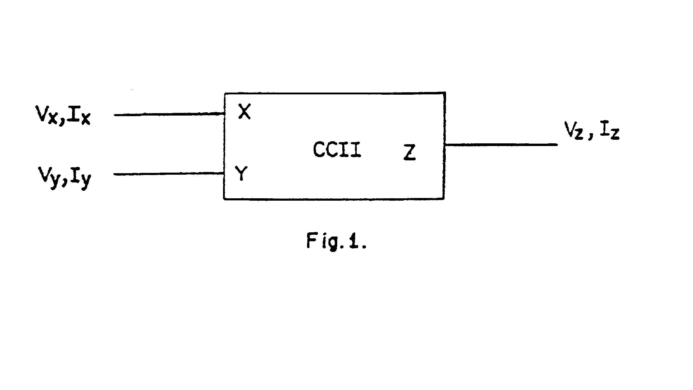
a technology of simulated circuit layout and conveyor, which is applied in the direction of process control, memory addressing/allocation/relocation, instruments, etc., can solve the problems of increasing the hardware count of signal processing, increasing the time used by the processor, and increasing the complexity of the system (digital signal processing)

Inactive Publication Date: 2005-08-16
COUNCIL OF SCI & IND RES
View PDF4 Cites 4 Cited by
  • Summary
  • Abstract
  • Description
  • Claims
  • Application Information

AI Technical Summary

Benefits of technology

[0083]FIG. 12 represents the effect of temperature variation over the LVCM's bandwidth

Problems solved by technology

The time used by the processor is actually too low.
This also increases the hardware count for the signal processing and hence, such a system (digital signal processing) is more complex which in turn returns to slow signal processing.
Moreover, the circuit structure is too complicated.
The input voltage buffer used is too complicated as it uses many CMs and many current summing nodes.
Low voltage operation is a the most favorable design technique for getting low power circuit structures, which, however, may not translate into l

Method used


Image

  • Simulated circuit layout for low voltage, low paper and high performance type II current conveyor
  • Simulated circuit layout for low voltage, low paper and high performance type II current conveyor
  • Simulated circuit layout for low voltage, low paper and high performance type II current conveyor

Examples


Embodiment Construction

[0097]For the proposed structure we have designed a application specific LVCMs and voltage buffers (VBs).

Low Voltage Current Mirror (LVCM)

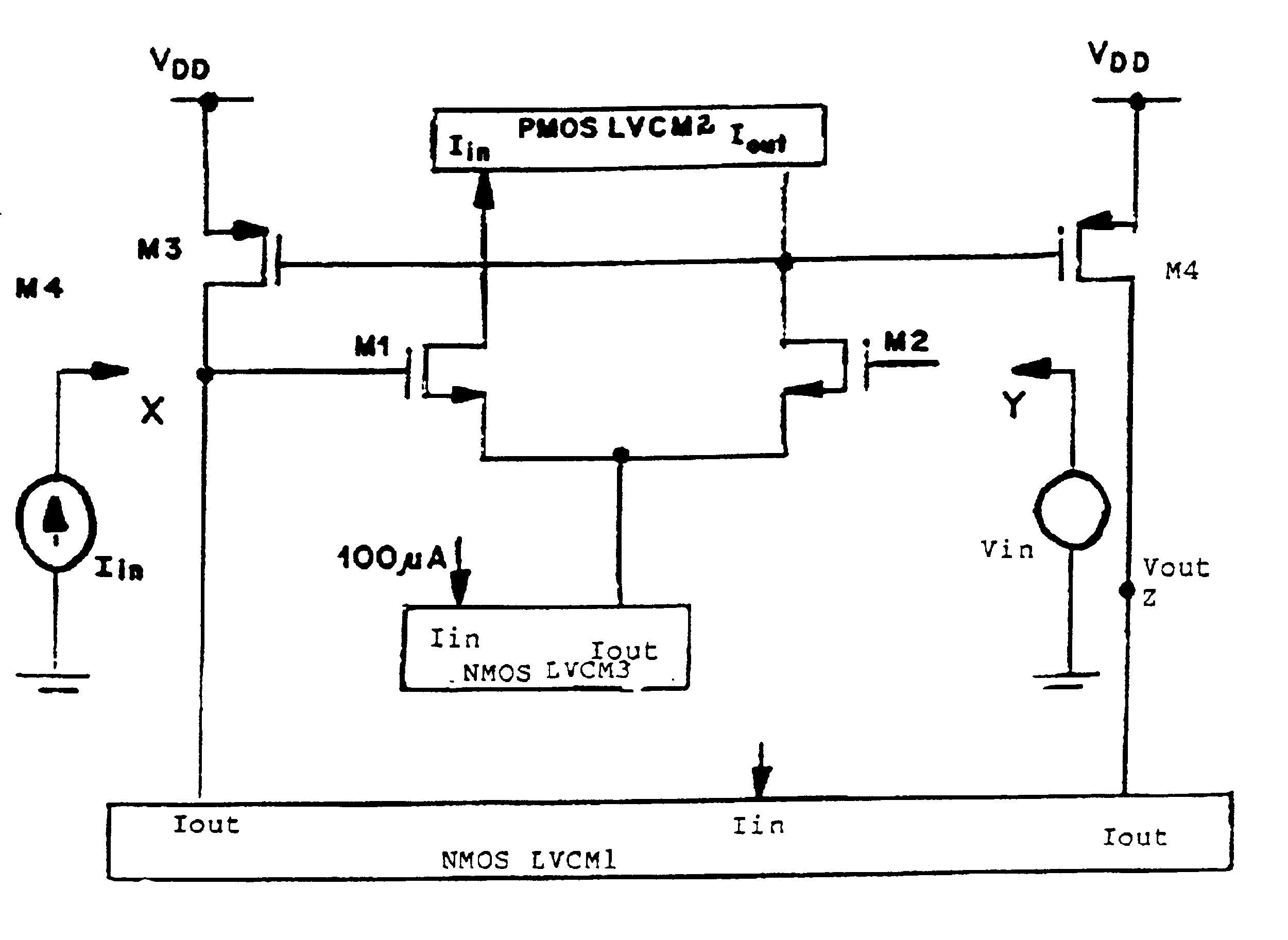
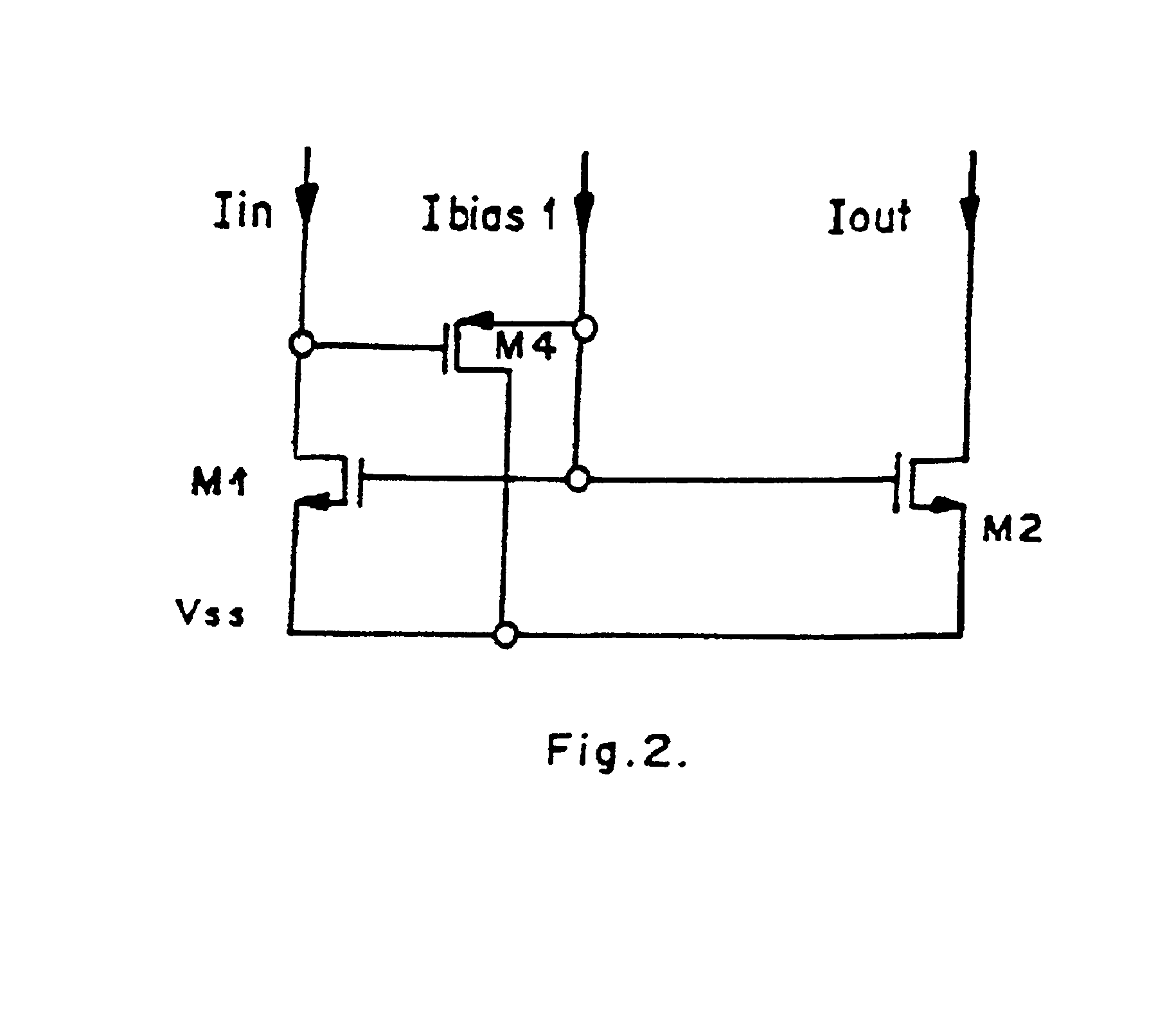
[0098]Refer to FIG. 2. The proposed circuit for implementation of LVCM uses the conventional CM structure in conjunction with a level shifter transistor at the input port to impart the high swing capability to the proposed CM. A capacitive and resistive compensation techniques were also used to enhance the bandwidth of the proposed CM. The CMs based on level shifter approach generally suffer from the flow of undesirable current at low input current levels. This current is called as offset current and is major bottleneck in LVCMs design. We introduce a adaptive biasing technique for the proposed LVCMs which increases the input voltage swing and decreases the offset current.

[0099]The design assumes the 0.8 μm technology parameters for p-Spice simulations. Transistor M4 is forced to operate in sub-threshold region by selecting a very low current to f...


PUM


Abstract

The present invention relates to a current conveyor circuit capable of operating at very low voltages, said circuit comprising: three LVCM's and four MOSFETS, wherein LVCM1 provides a constant bias current to flow through M3, if port X is kept open and the difference between the bias current and the injected current flows through M3 if a current is injected into port X, which gets reflected at port Z due to the action of LVCM1, M3 and M4, LVCM2 maintains the drain currents of M1 and M2 constant, and LVCM3 maintains a constant tail current in the circuit.

Description

FIELD OF THE INVENTION[0001]The present invention relates to a simulated circuit layout for low voltage, low power and high performance type II current conveyor.BACKGROUND OF THE INVENTION[0002]Analog world is an exciting field having great potential for commercial exploitation. Most of the things do occur in nature in analog way and the processing the signal in analog domain is the natural way of signal processing. This processing does not require conversion to any other domain and hence is natural and fast. Contrary to this, the processing of the signal in digital domain requires signal conversion into digital domain from analog domain and then back conversion into analog mode after processing. The processing in digital domain may be fast enough but the processing time is actually controlled by the devices used for analog to digital and digital to analog conversion. The time used by the processor is actually too low. This also increases the hardware count for the signal processing...

Claims


Application Information

Patent Timeline
IPC IPC(8): H03F3/343H03F3/345
CPCH03F3/345
Inventor RAJPUT, SHER SINGHJAMUAR, SUDHANSHU SHEKHAR
Owner COUNCIL OF SCI & IND RES
Why Eureka
Try Eureka