
Laser-driven cleaning using reactive gases

Inactive Publication Date: 2005-08-23
ORAMIR SEMICON EQUIP
View PDF4 Cites 1 Cited by
  • Summary
  • Abstract
  • Description
  • Claims
  • Application Information

AI Technical Summary

Benefits of technology

[0011]It is an object of the present invention to provide methods and apparatus for efficient removal of contaminants from solid-state surfaces, and particularly for removal of microscopic particles from semiconductor wafers and other elements used in semiconductor device production. The wafers may be bare, or they may have layers formed on their surface, whether patterned or unpatterned.
[0012]It is a further object of some aspects of the present invention to provide methods and apparatus for removal of contaminants from wafer surfaces in a manner that reduces the likelihood of damage to the surface.
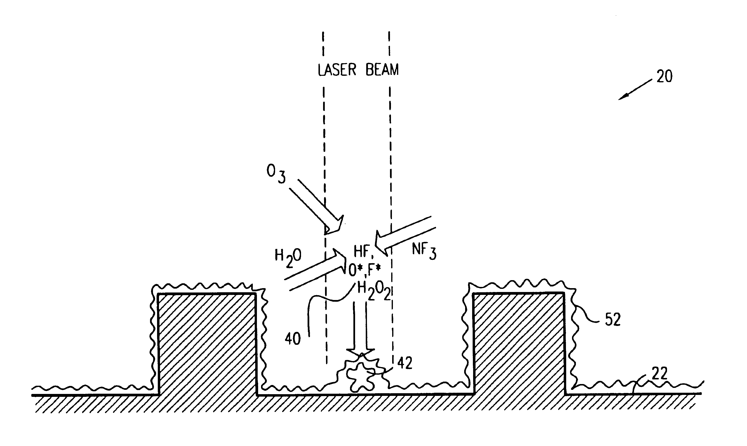
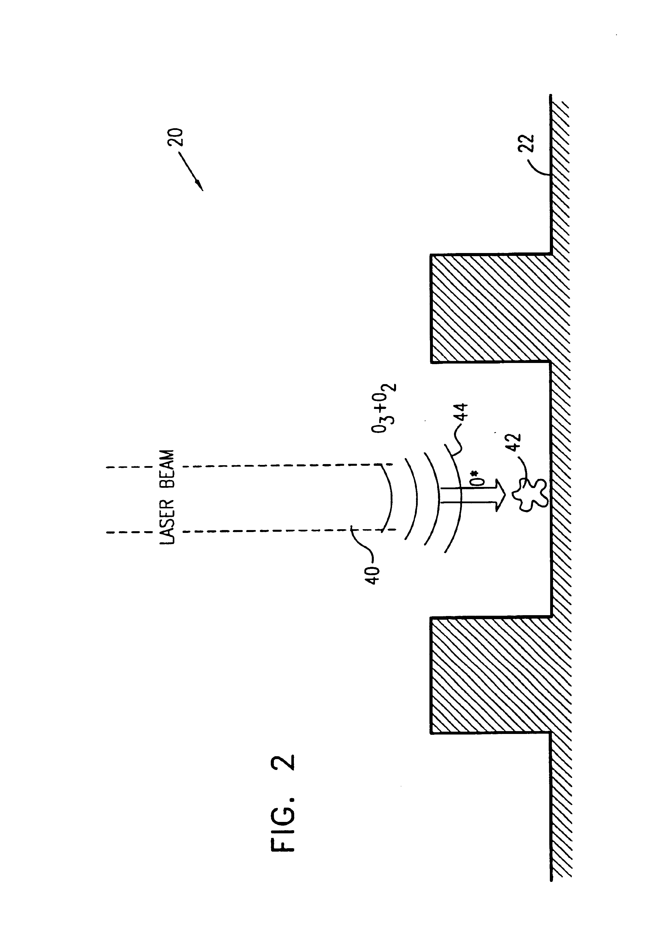
[0013]In preferred embodiments of the present invention, a laser beam excites a process gas in proximity to a wafer surface, for the purpose of removing contaminants from the surface. Excitation of the gas generates reactive species, typically atomic and / or molecular radicals, which rapidly oxidize the contaminants, facilitating their removal. This chemical reaction cooperates with gas-dynamic effects, such as a blast wave, created by the intense laser irradiation. These combined effects substantially reduce the laser energy flux that must be applied to the wafer surface itself in order to achieve complete removal of the contaminants, thereby reducing the likelihood that the surface will be damaged in the process.

Problems solved by technology

As the critical dimensions of circuit features become ever smaller, the presence of even a minute foreign particle on the wafer during processing can cause a fatal defect in the circuit.
One particularly bothersome type of contamination that is found on semiconductor wafers is residues of photoresist left over from a preceding photolithography step.

Method used


Image

  • Laser-driven cleaning using reactive gases
  • Laser-driven cleaning using reactive gases
  • Laser-driven cleaning using reactive gases

Examples


Embodiment Construction

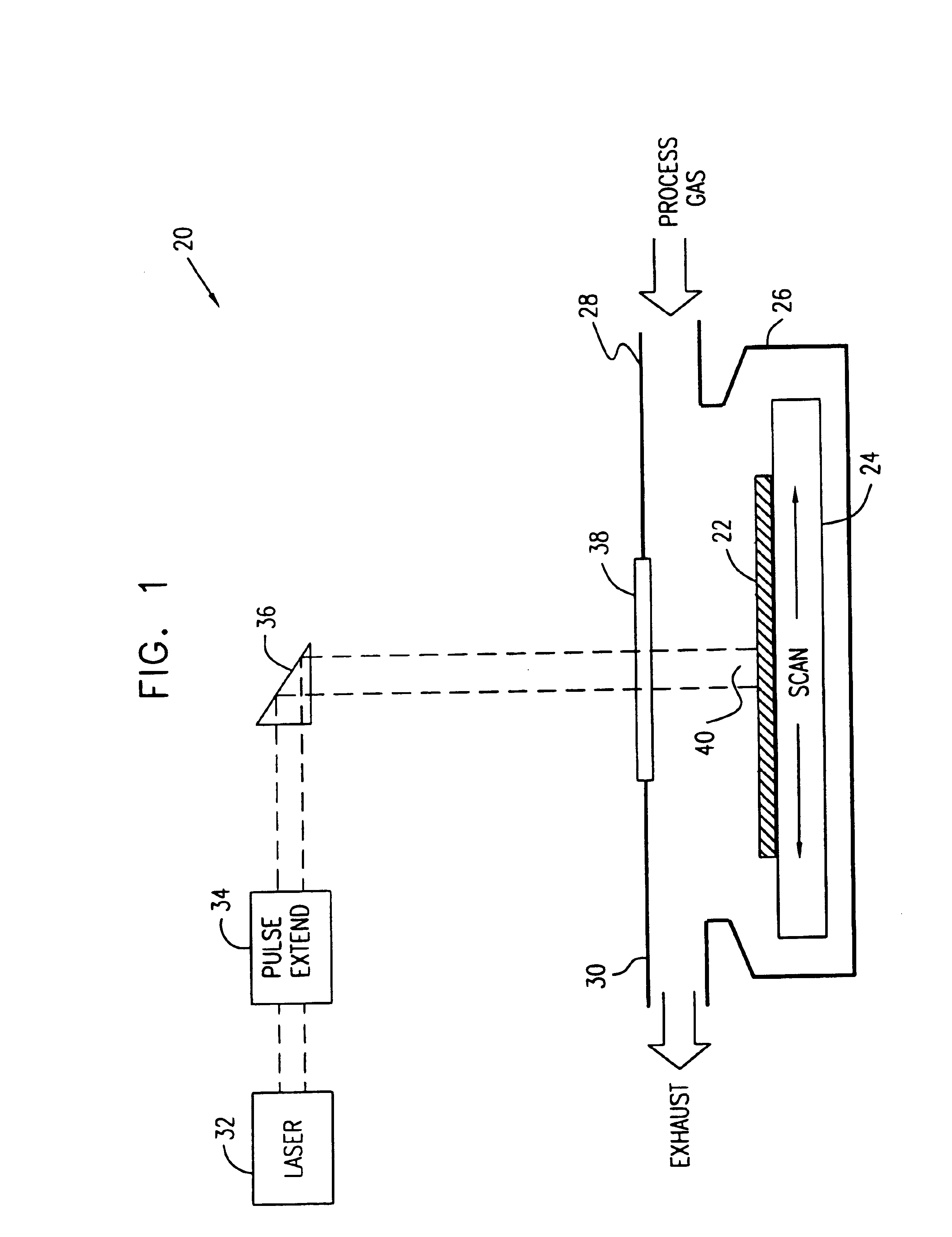
[0045]FIG. 1 is a schematic side view of a system 20 for removal of contaminants from the surface of a semiconductor wafer 22, in accordance with a preferred embodiment of the present invention. The wafer is placed on a scanning stage 24 in a chamber 26. A process gas flows into the chamber through an inlet port 28, while waste gas, including residues of contaminants removed from wafer 22, are exhausted through an outlet port 30. Various designs that may be used for chamber 26 are known in the art. A particularly advantageous design is described in PCT patent application PCT / IL99 / 00701, which is assigned to the assignee of the present patent application, and whose disclosure is incorporated herein by reference. In this design, stage 24 comprises a rotation stage, and ports 28 and 30 are located in close proximity to an area on the wafer at which laser-induced contaminant removal takes place. Optionally, additional gas ports (not shown in the figure) are provided for injecting a lami...


PUM

PropertyMeasurementUnit
Energyaaaaaaaaaa
Semiconductor propertiesaaaaaaaaaa

Abstract

A method and apparatus for removing contaminants from the surface of a substrate. An explosive medium is introduced into a vicinity of the substrate, and a beam of electromagnetic energy is directed toward the substrate. Absorption of the electromagnetic energy causes the explosive medium both to generate a blast wave and to form reactive species, the blast wave and the reactive species cooperating to remove the contaminants from the surface substantially without damage to the surface itself.

Description

CROSS REFERENCE TO RELATED APPLICATION(S)[0001]This application is a divisional of U.S. patent application Ser. No. 09 / 564,914, filed May 4, 2000 now U.S. Pat. No. 6,627,846, which claims priority of provisional application No. 60 / 172,299, filed Dec. 16, 1999.FIELD OF THE INVENTION[0002]The present invention relates generally to processing of semiconductor devices, and specifically to methods and apparatus for removal of foreign particles from semiconductor wafers and masks.BACKGROUND OF THE INVENTION[0003]Removal of contaminants from semiconductor wafers is a matter of great concern in integrated circuit manufacturing. As the critical dimensions of circuit features become ever smaller, the presence of even a minute foreign particle on the wafer during processing can cause a fatal defect in the circuit. Similar concerns affect other elements used in the manufacturing process, such as lithographic masks.[0004]Various methods are known in the art for stripping and cleaning foreign mat...

Claims


Application Information

Patent Timeline
IPC IPC(8): B08B7/00H01L21/67H01L21/00H01L21/68
CPCB08B7/0035B08B7/0042H01L21/67028H01L21/67288H01L21/681H01L21/67069
Inventor YOGEV, DAVIDLIVSHITZ BUYANER, BORIS
Owner ORAMIR SEMICON EQUIP
Learn More