Micromovement measuring device and method of movement process conversion to an electric signal

a micro-movement and measuring device technology, applied in the field of instruments, can solve the problems of limited use of x-ray interferometers, inapplicability of x-ray interferometers, and narrow dynamic range, so as to eliminate electroerosive processes at working surfaces and raise the sensitivity of a measuring device

Inactive Publication Date: 2005-08-30
A METRICS
View PDF2 Cites 4 Cited by
  • Summary
  • Abstract
  • Description
  • Claims
  • Application Information

AI Technical Summary

Benefits of technology

[0012]The object of the proposed invention is to raise the sensitivity of a measuring device in a wide dynamic range by eliminating elastic microdeformation

Problems solved by technology

However, in the cases which lie outside metrology and investigations of crystal structure of materials, the use of X-ray interferometers does not find application owing to high sluggishness of the sensitive elements employed, cumbersome apparatus design, complexity, and high price.
The limitation of their use is attributed to the fact that raising the sensitivity of these transducers necessarily leads to narrowing of the dynamic range because of non-linearity of their analog measuring characteristics.
The disadvantage

Method used


Image

  • Micromovement measuring device and method of movement process conversion to an electric signal
  • Micromovement measuring device and method of movement process conversion to an electric signal

Examples


Embodiment Construction

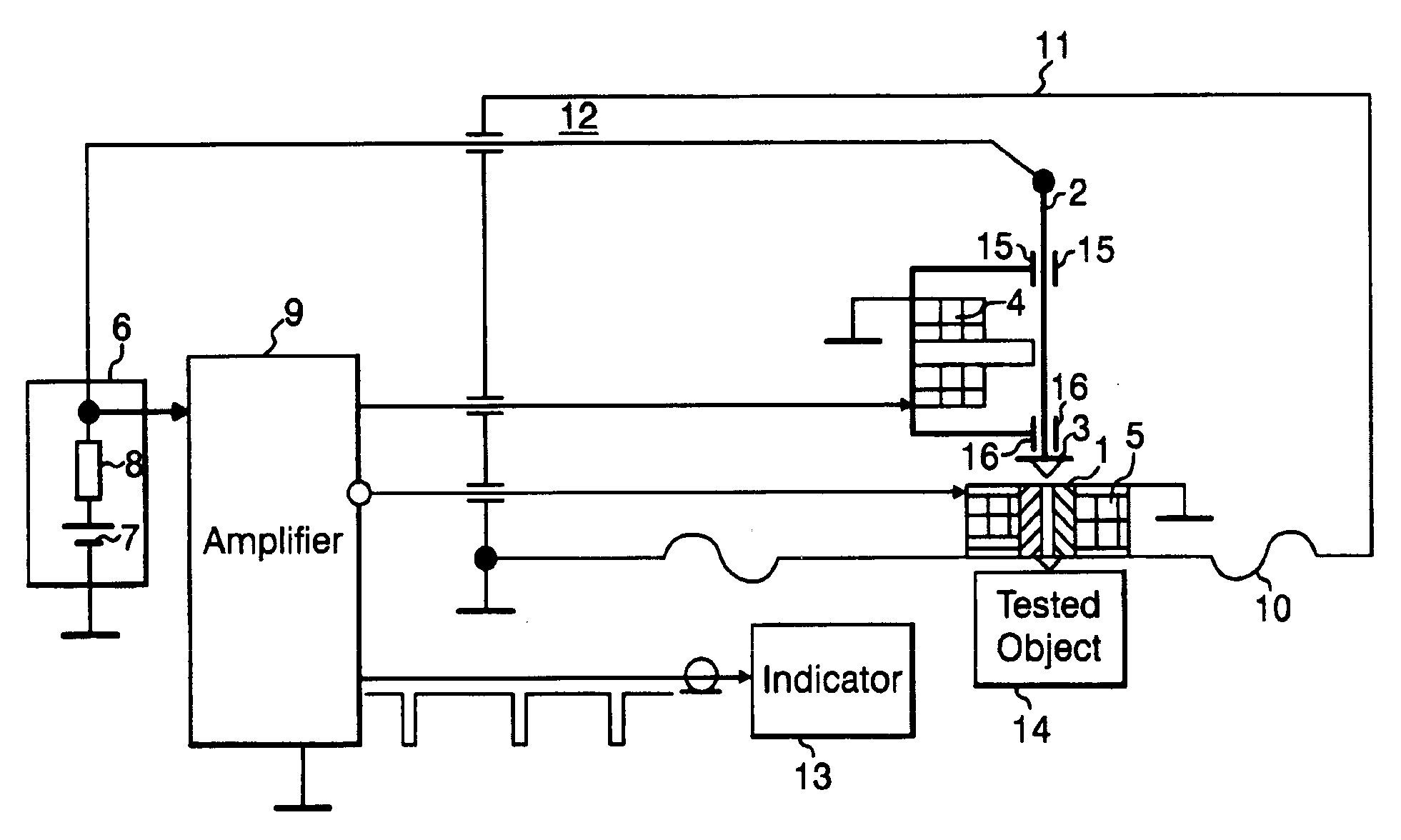
[0019]The principal diagram of the device is given in FIG. 1.

[0020]The micromovement measuring device consists of a sensitive element 1, a measuring element 2 with a washer 3, and a fixing electromagnet 4. The measuring element 2 is capable of longitudinal movement between guides 15, 16 due to movement of the washer 3 away from or toward the sensitive element 1 in response to attractive magnetic forces applied to the washer 3 from either of the fixing electromagnet 4 or from the pulling electromagnet 5, respectively. The measuring element 2 is electrically connected to a signal conditioner 6 which includes an operating voltage source 7 and a current limiter 8, such that a voltage from the voltage source 7 is applied to the measuring element 2. Accordingly, the voltage differential across a gap between the measuring element 2 and the sensitive element 1 creates a field electronic emission current therebetween. A first output of the signal conditioner 6 is connected to the input of an...


PUM


Abstract

A micromovement measuring device records creeping and dynamic infraprocesses both of natural and artificial origin, including seismic processes or infrasound and gravitational waves. The device has a sensitivity for measuring in a wide dynamic range. The device includes a measuring element, a sensitive element, a membrane, a signal conditioner, a fixing electromagnet, and a pulling electromagnet. The pulling electromagnet is located on the membrane which increases the range of the measurable movements. A hermetic housing prevents the formation of oxides or similar films at the working surfaces of the measuring and sensitive elements. A method of converting movement to electric signals is performed by the device, which takes an electronic field emission current to be a characteristic of quantization, and so movements in the range of Angstroms may be recorded.

Description

BACKGROUND OF THE INVENTION[0001]1. Field of the Invention[0002]The invention relates to the field of instrumentation, in particular, to measurement of micromovement, and may be used for measuring, detecting, and recording creeping and dynamic infraprocesses in nature, engineering, and bionics; for example, for recording baric, thermal, and hygrometric tendencies in meteorology; for recording creeping of engineering structures; for testing leakproofness of small and large installations and in security systems; as well as for recording seismic, infrasound, and gravitation waves. In bionics, the proposed device may be used as a part of tactile sensitivity, in bionic prostheses, bionic robots, and zoo-robots.[0003]2. Description of the Related Art[0004]To address the above problems, measuring systems should have maximum possible sensitivity up to Angstrom units (Å)-wide dynamic ranges and low sluggishness.[0005]At present, the highest sensitivity and widest dynamic ranges are provided ...

Claims


Application Information

Patent Timeline
IPC IPC(8): G01B7/16G01B7/00G01M99/00G01V1/18
CPCG01B7/16G01V7/12
Inventor BEKERS, LEONIDSLUBGINS, BONIFATIJSFINKELSHTEINS, JEHEZKELISNUROVS, JURISPIORUNSKIS, ALEXANDRA
Owner A METRICS
Why Eureka
Try Eureka