Transmissive and reflective type liquid crystal display

a liquid crystal display and reflective technology, applied in non-linear optics, instruments, optics, etc., can solve the problems of reducing light transmissivity by 50%, large volume and high power consumption, and heavy weight, and achieve enhanced transmissivity, enhanced overall light efficiency, and simple structure

Inactive Publication Date: 2005-08-30
SAMSUNG DISPLAY CO LTD
View PDF3 Cites 25 Cited by
  • Summary
  • Abstract
  • Description
  • Claims
  • Application Information

AI Technical Summary

Benefits of technology

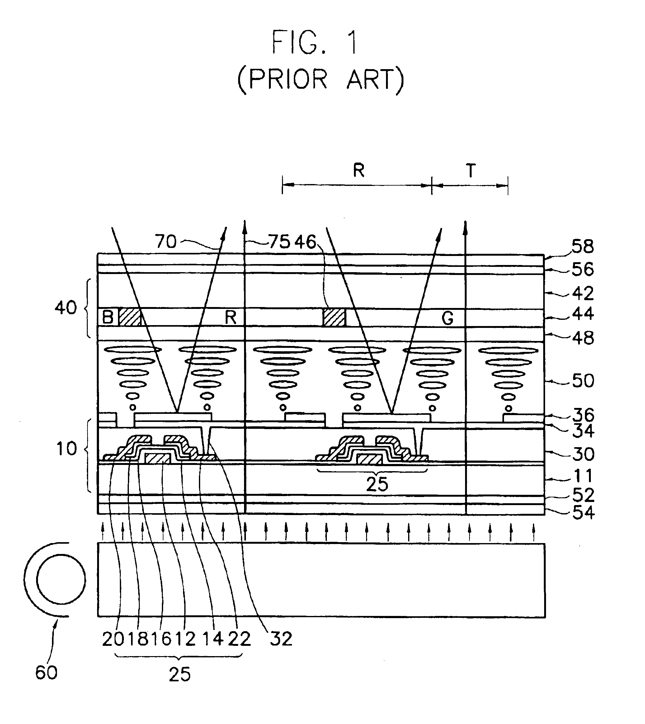
[0030]Accordingly, the present invention is to solve the aforementioned problems of the conventional art, and it is an object of the present invention to provide a transmissive and reflective type LCD capable of simplifying a structure of a liquid crystal cell and decreasing light loss in the transmission mode.
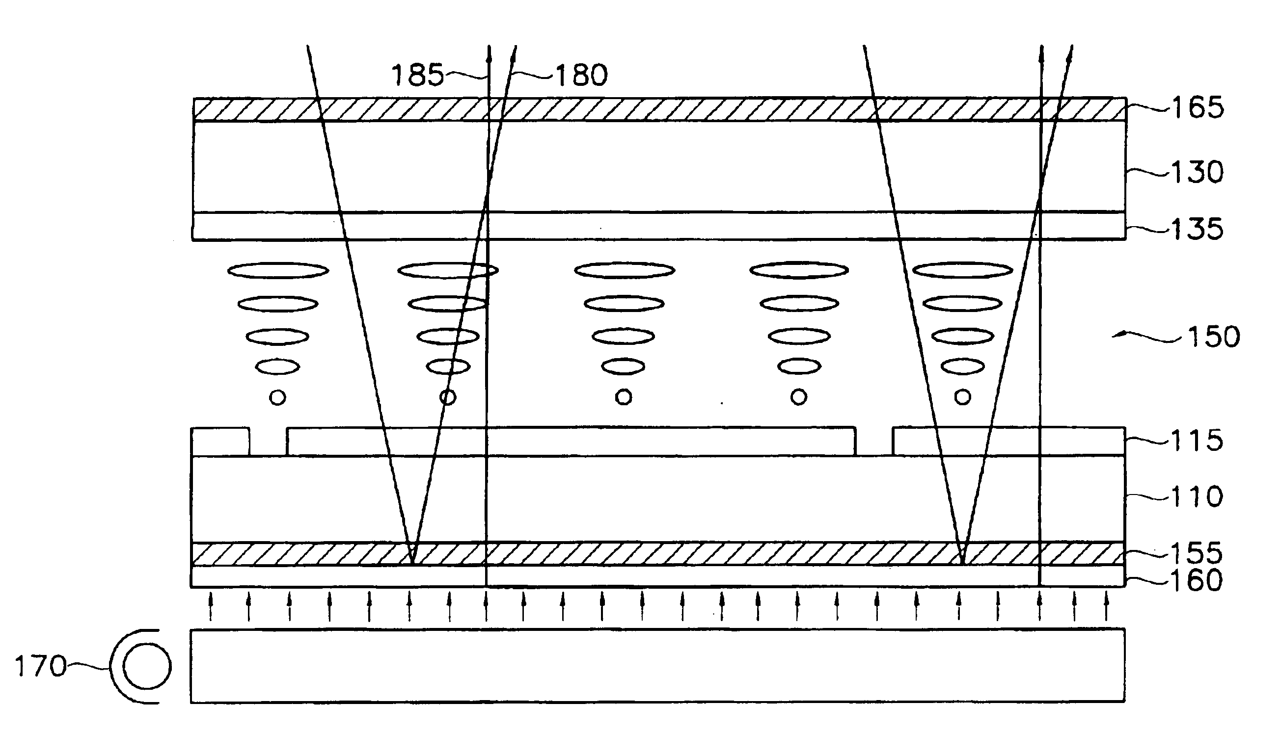
[0037]The transmissive and reflective type LCD of the invention has no reflection electrode within LC cell and no ¼-wavelength phase difference plate on each of the upper substrate (second substrate) and the lower substrate (first substrate). Hence, compared with the conventional transmissive and reflective type LCD, the transmissive and reflective type LCD of the present invention can be made in a more simple structure.
[0038]Further, it is possible that the transflective film of partially being transmitted and reflecting incident light performs both functions of the reflection electrode and the transparent electrode at the same time, and a recycling process of light is lastingly generated, so that light loss is not generated in the transmission mode. Accordingly, compared with the conventional transmissive and reflective type LCD, the transmissive and reflective type LCD of the invention has an enhanced transmissivity. Also, since the transmissive and reflective type LCD of the invention does not utilize the ¼ wavelength phase difference plate, the light that is incident from the backlight and is then reflected by metal regions of LC cell is recycled and again used, so that it becomes possible to enhance an overall light efficiency.
[0039]Furthermore, since the optical conditions applied to the liquid crystal of the conventional transmissive and reflective type LCD can be identically applied to that of the transmissive and reflective type LCD of the present invention, degeneration in the reliability of the liquid crystal can be prevented.

Problems solved by technology

The CRT used in an image display such as a television receiver and a monitor, etc., has the highest market share in an aspect of displaying quality and economical efficiency, but also has many disadvantages such as heavy weight, large volume and high power consumption.
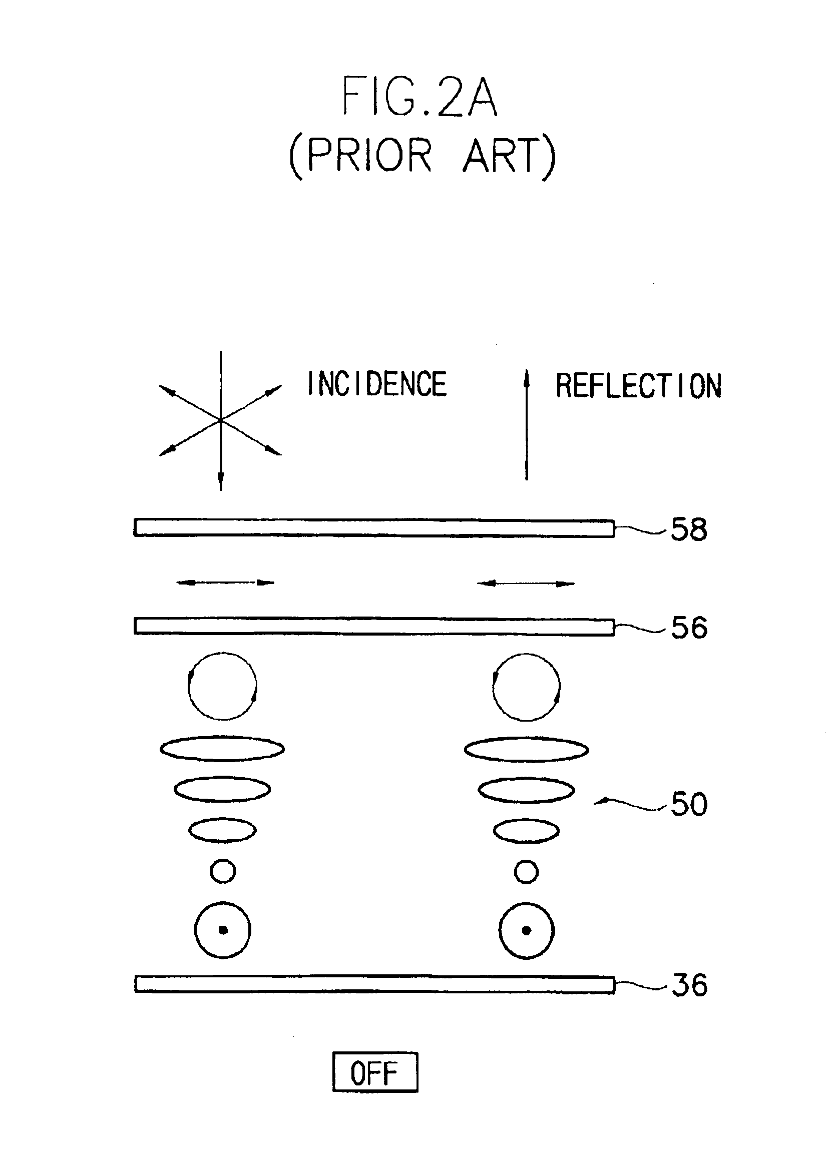
Also, since the polarization characteristic in the transmission mode causes a light loss of 50%, there are drawbacks in that a light transmissivity decreases by 50% and a contrast ratio (C / R) is lowered.
Accordingly, there are problems in that the manufacturing process becomes difficult and degeneration in the reliability of the liquid crystal is caused.

Method used


Image

  • Transmissive and reflective type liquid crystal display
  • Transmissive and reflective type liquid crystal display
  • Transmissive and reflective type liquid crystal display

Examples


third embodiment

[0109]FIG. 12 is a sectional view of a transmissive and reflective type LCD in accordance with the present invention, especially shows a thin film transistor (TFT) LCD having top-gate structure.

[0110]Referring to FIG. 12, a transmissive and reflective type LCD includes a first substrate 300, a second substrate 350 facing the first substrate 300, a liquid crystal layer 360 disposed between the first substrate 300 and the second substrate 350, and a backlight assembly disposed below the first substrate 300.

[0111]The first substrate 300 includes a plurality of gate lines (not shown) and a plurality of data lines (not shown), pixel electrodes 334 and thin film transistors (TFTs) 325 on a first insulating substrate 310. The data lines and gate lines are arranged in a matrix shape on the first insulating substrate 310, Each pixel electrode and each TFT 325 are disposed on a intersection of the data and gate lines. The second substrate 350 includes a second insulating substrate 352, color ...

fourth embodiment

[0118]FIG. 13 is a sectional view of a transmissive and reflective type LCD in accordance with the present invention, and FIG. 14 is a plane view of a first substrate of FIG. 13.

[0119]Referring to FIG. 13 and FIG. 14, the transmissive and reflective type LCD includes a first substrate 412a, a second substrate 412b facing the first substrate 412a, a liquid crystal layer (LC, not shown) disposed between the first substrate 412a and the second substrate 412b, and a backlight assembly 490 disposed below the first substrate 412a.

[0120]A display cell array circuit 450, a data driver circuit 460, a gate driver circuit 470, a first external terminal 463 for connecting the data driver circuit 460 and a second external terminal 472 for connecting the gate driver circuit 470. The liquid crystal layer (LC) is disposed between the first substrate 412a having color filters and the second substrate 412b having transparent common electrode (CE). According to an alignment direction of the liquid cr...


PUM

PropertyMeasurementUnit
reflectivityaaaaaaaaaa
refractive indexaaaaaaaaaa
thicknessaaaaaaaaaa

Abstract

Disclosed is a transmissive and reflective type LCD. In the LCD, a second substrate faces a first substrate. Liquid crystal layer is formed between the first and second substrate. A first polarizing plate is formed on outer surface of the first substrate. A second polarizing plate is formed on outer surface of the second substrate. A backlight is arranged at a rear side of the first polarizing plate. A transparent transflective film is arranged between the first polarizing plate and the backlight and has a plurality of layers where a first and a second layer each having different refractivity indexes are alternatively stacked. The transparent transflective film partially reflects and transmits incident light. By a restoring process occurring between the transflective film and the backlight, a predetermined amount of the incident light is transmitted through the transflective film repeatedly, so that transmissivity and light efficiency are enhanced.

Description

CROSS-REFERENCE OF RELATED APPLICATIONS[0001]This application is a Continuation-in-part application of “TRANSMISSIVE AND REFLECTIVE TYPE LIQUID CRYSTAL DISPLAY”, by the present inventor, Ser. No. 10 / 183,143, filed on Jun. 26, 2002 now U.S. Pat No. 6,831,719, the contents of which are herein incorporated by reference in their entirety. The application also relies for priority upon Korean Patent Application No.2001-80714 filed on Dec. 18, 2001 and Korean Patent Application No.2002-39499 filed on Jul. 8, 2002, the contents of which are herein incorporated by reference in their entirety.BACKGROUND OF THE INVENTION[0002]1. Field of the Invention[0003]The present invention relates to a liquid crystal display, and more particularly, to a transmissive and reflective type liquid crystal display in which the display operation is carried out in a reflection mode of a low power consumption at a bright place where a light amount is abundant and the display operation is also carried out in a tran...

Claims


Application Information

Patent Timeline
Patent Type & Authority Patents(United States)
IPC IPC(8): G02F1/13G02F1/1335G02F1/13357
CPCG02F1/133555G02F1/133615G02F2001/133567G02F1/133567
Inventor JANG, YONG-KYUKIM, HYUNG-GUELYOON, JONG-SOOLEE, DONG-HO
Owner SAMSUNG DISPLAY CO LTD
Why Eureka
Try Eureka