Nitrogen oxide reducing system for diesel engine and nitrogen gas generating device

a technology of nitrogen gas generation device and nitrogen oxide reduction system, which is applied in the direction of fluid pressure control, separation process, instruments, etc., can solve the problem of almost impossible removal

Inactive Publication Date: 2005-09-06
OOE TOSHIAKI +1
View PDF9 Cites 12 Cited by
  • Summary
  • Abstract
  • Description
  • Claims
  • Application Information

AI Technical Summary

Benefits of technology

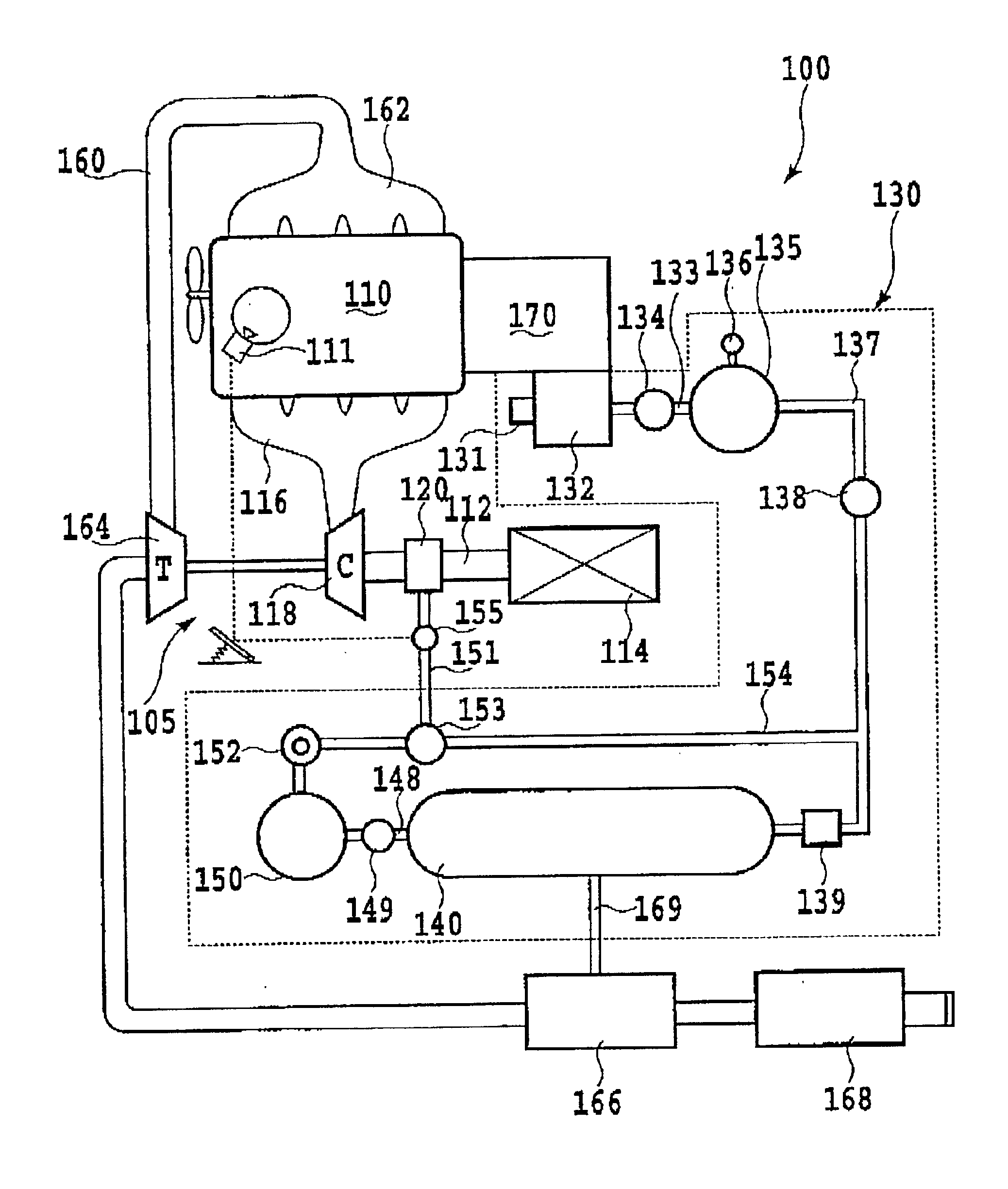
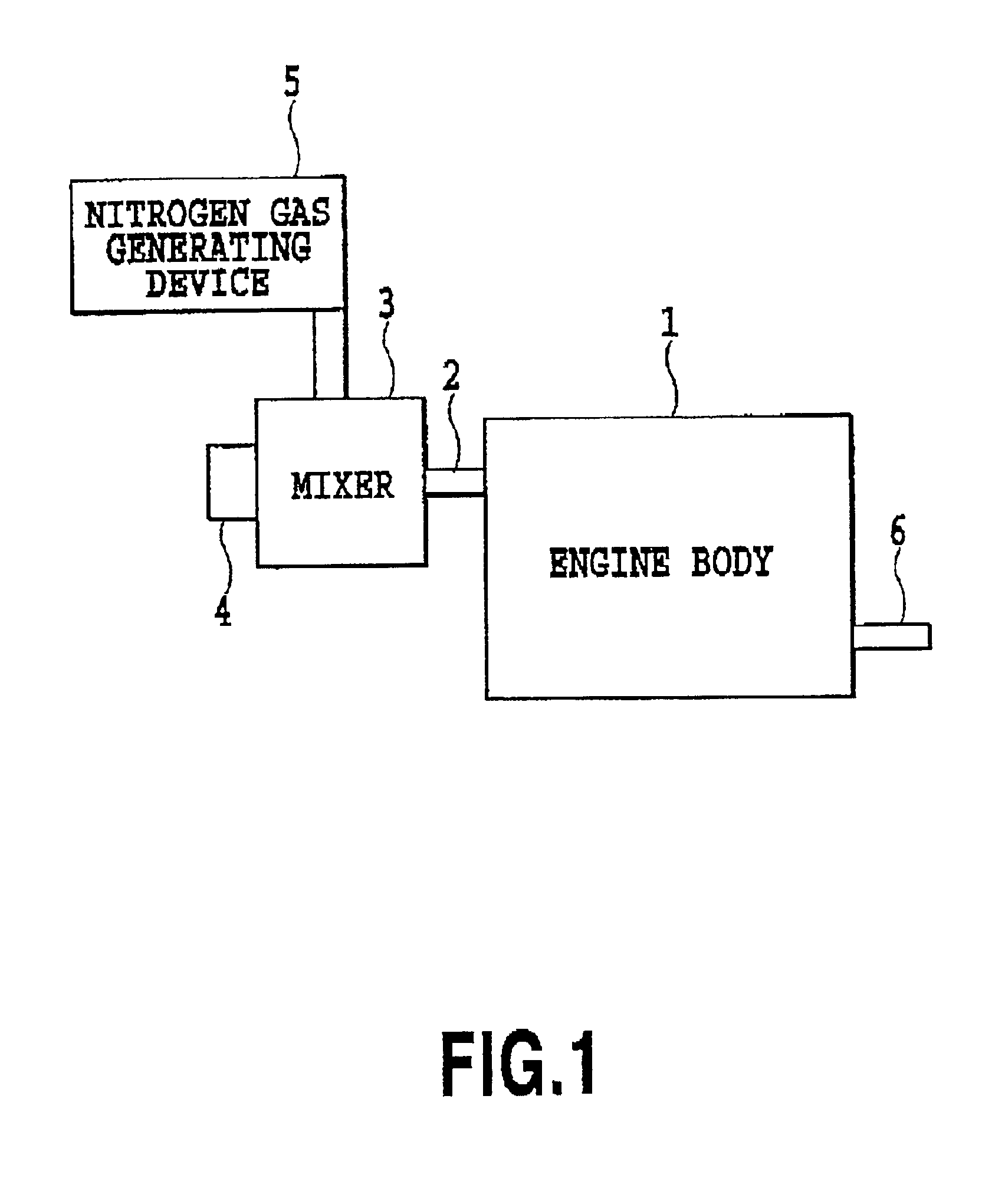
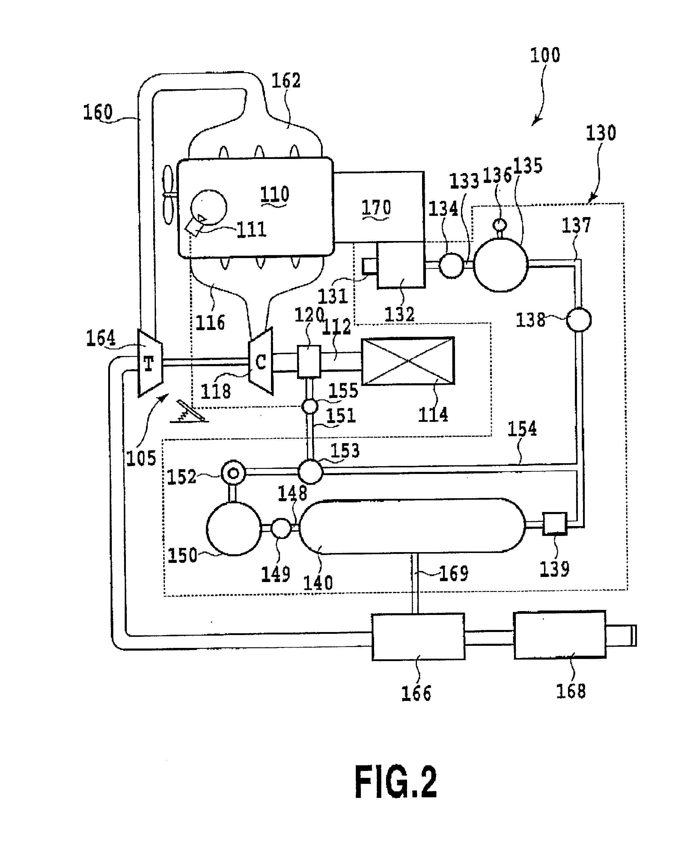
[0013]It is an object of the present invention to solve the problems in the prior art set forth above and to provide a nitrogen oxide reducing system of a diesel engine which can reduce nitrogen oxide contained in an exhaust gas of the diesel engine, thereby adapting to restrictions.

Problems solved by technology

It is almost impossible to remove once nitrogen in the air is introduced into a combustion chamber and is converted into nitrogen oxide.

Method used


Image

  • Nitrogen oxide reducing system for diesel engine and nitrogen gas generating device
  • Nitrogen oxide reducing system for diesel engine and nitrogen gas generating device
  • Nitrogen oxide reducing system for diesel engine and nitrogen gas generating device

Examples


experiment 1

)

[0074]Employing an engine of Mitsubishi Heavy Industries Ltd. (Type: 6D34-TE1, displacement: 5861 cc, with turbocharger), the nitrogen gas of about 89% in concentration is supplied at 100 liters per minute. Reduction ratio of nitrogen oxide is shown in the following table 1.

[0075]

TABLE 1Nitrogen OxideIdling2000 r.p.m.System Not provided101vol ppm172vol ppmSystem Provided80vol ppm153vol ppmReduction Ratio21%11%

experiment 2

)

[0076]Employing an engine of Mitsubishi Heavy Industries Ltd. (Type: 6D34-TE1, displacement exhaust amount: 5861 cc, with turbocharger), the nitrogen gas of about 98.5 concentration is supplied at 100 liters per minute. Reduction ratio of nitrogen oxide is shown in the following table 2.

[0077]

TABLE 2Nitrogen OxideIdling2000 r.p.m.System Not Provided188vol ppm219vol ppmSystem Provided126vol ppm188vol ppmReduction Ratio32%14%

experiment 3

)

[0078]Employing an engine of Isuzu Motor Co. Ltd. (Type: 4BDI, displacement: 4100 cc, with turbocharger), the nitrogen gas of about 93% in concentration is supplied at 220 liters per minute. Reduction ratio of nitrogen oxide is shown in the following table 2.

[0079]

TABLE 3Nitrogen OxideIdling2000 r.p.m.System Not Provided172vol ppm375vol ppmSystem Provided57vol ppm274vol ppmReduction Ratio67%27%

[0080]It should be noted that the foregoing experiments 1) to 3) were performed by Shikoku Keisoku Kogyo K. K. Experiments 4) to 6).

[0081]Employing an engine of Komatsu Ltd. (Type; SAA6D95L, displacement; 4890 cc, with turbocharger and intercooler), for Experiment 4) the nitrogen gas of about 90% in concentration is supplied at 110 liters per minute, for Experiment 5) the nitrogen gas of about 91.5% in concentration is supplied at 120 liters per minute, and for Experiment 6) the nitrogen gas of about 95% in concentration is supplied at 350 liters per minute. Experiments were performed for mea...


PUM

PropertyMeasurementUnit
diameteraaaaaaaaaa
diameteraaaaaaaaaa
temperatureaaaaaaaaaa

Abstract

A nitrogen oxide reducing system of a diesel engine can reduce nitrogen oxide contained in an exhaust gas of the diesel engine and whereby cab adapt to a restriction. At a tip end of a mixer, air holes required by the engine are formed, a nitrogen gas generating device for increasing concentration of nitrogen in the air is mounted to introduce nitrogen into the mixer, the mixer is mounted to the induction opening of the engine at opposite side of the air hole to introduce increased amount of nitrogen to prevent oxidation of nitrogen and discharge nitrogen.

Description

BACKGROUND OF THE INVENTION[0001]1. Field of the Invention[0002]The present invention relates generally to a nitrogen oxide reducing system for a diesel engine and a nitrogen gas generating device for reducing a nitrogen oxide in an exhaust gas by adjusting a nitrogen concentration in induction air. More particularly, the present invention relates to a system for preventing oxidation of nitrogen by mounting a nitrogen gas generating device on a mixer for mixing air in the mixer with nitrogen supplied from the nitrogen gas generating device for increasing nitrogen concentration.[0003]2. Description of the Related Art[0004]Currently, as a part of environment protection policy, restriction for discharge of exhaust gas from a diesel engine for suppressing air pollution is becoming more and more strict year by year. Particularly, even in a large size diesel engine to be employed in a special purpose vehicle, such as a construction machine, industrial machine or the like, severe regulatio...

Claims


Application Information

Patent Timeline
Patent Type & Authority Patents(United States)
IPC IPC(8): B01D53/92F01N3/02F01N3/023F01N3/029F01N3/022F02M25/00F02M25/12F02B37/00
CPCB01D53/92F01N3/02F01N3/022F01N3/029F01N3/0293F02M25/00F01N2240/10F02B37/00F02M25/12
Inventor OOE, TOSHIAKIIIMA, TAKANORI
Owner OOE TOSHIAKI
Why Eureka
Try Eureka