Electric circuit for portable heater

a portable heater and electric circuit technology, applied in the field of electric circuits for heaters, can solve the problems of high fan speed, large noise, and unnecessary noise at the lower heat output, and achieve the effects of reducing the fan speed, effective control and safe operation, and convenient manufacturing

Inactive Publication Date: 2005-09-06
TATEISHI ART K
View PDF11 Cites 26 Cited by
  • Summary
  • Abstract
  • Description
  • Claims
  • Application Information

AI Technical Summary

Benefits of technology

[0016]Several advantages are achieved with the heating circuit of the present invention. The fan motor is easily manufactured and cooperates with the heating elements to provide effective control and safe operation. In a preferred embodiment automatic adjustment of the fan motor speed as the heat output increases or decreases effectively matches the fan motor speed with the heat output. By reducing the fan speed as the power of the heater decreases, the discharge temperature of the air as it leaves the heater is higher. Also the lower operating speed of the motor reduces motor noise and is less intrusive. The automatic adjustment of the fan motor speed is achieved by using the heating elements to vary the current to the fan motor. Thus, no additional elements have been added to the heating circuit to achieve the automatic speed adjustment of the fan.

Problems solved by technology

This amount of heat generation requires a substantial airflow to maintain a low operating temperature with the plastic molded heater housing.
A high fan speed is required at the maximum heat output and produces a significant amount of noise.
As the fan runs at high speed for all heat output conditions, unnecessary noise is produced at lower heat outputs.
Multispeed motors and / or resistors can be used to drop the voltage to the fan motor but significantly add to the cost of the heater and complicate the manufacturing process.
These high speed, low current fans include many windings of small gauge wire which is prone to breakage and is more expensive relative to heavier gauge magnetic motor wire.
As such, these motors represent a major cost component of the heater.
The purchase of a portable heater remains a price sensitive purchase as the heater is typically solving a specific problem requiring a temporary solution.

Method used


Image

  • Electric circuit for portable heater
  • Electric circuit for portable heater
  • Electric circuit for portable heater

Examples


Embodiment Construction

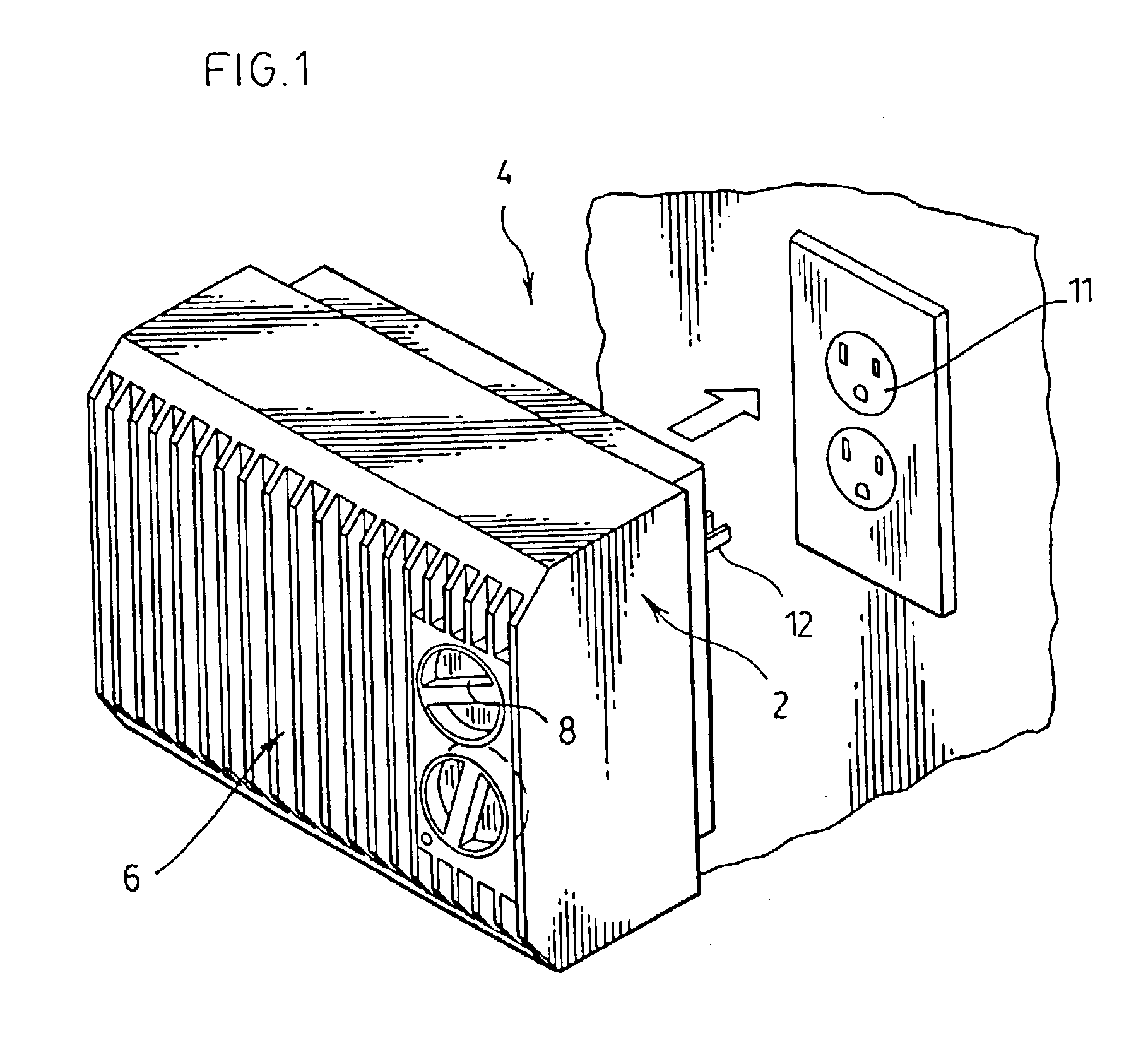
[0028]The portable heater 2 of FIG. 1 includes an air inlet 4, an air outlet 6, a multi-position switch 8 and an electrical plug 12 for connecting the portable heater to the electrical supply 11. Interior to the housing 12 is an electrical circuit for producing heat and controlling of the fan.

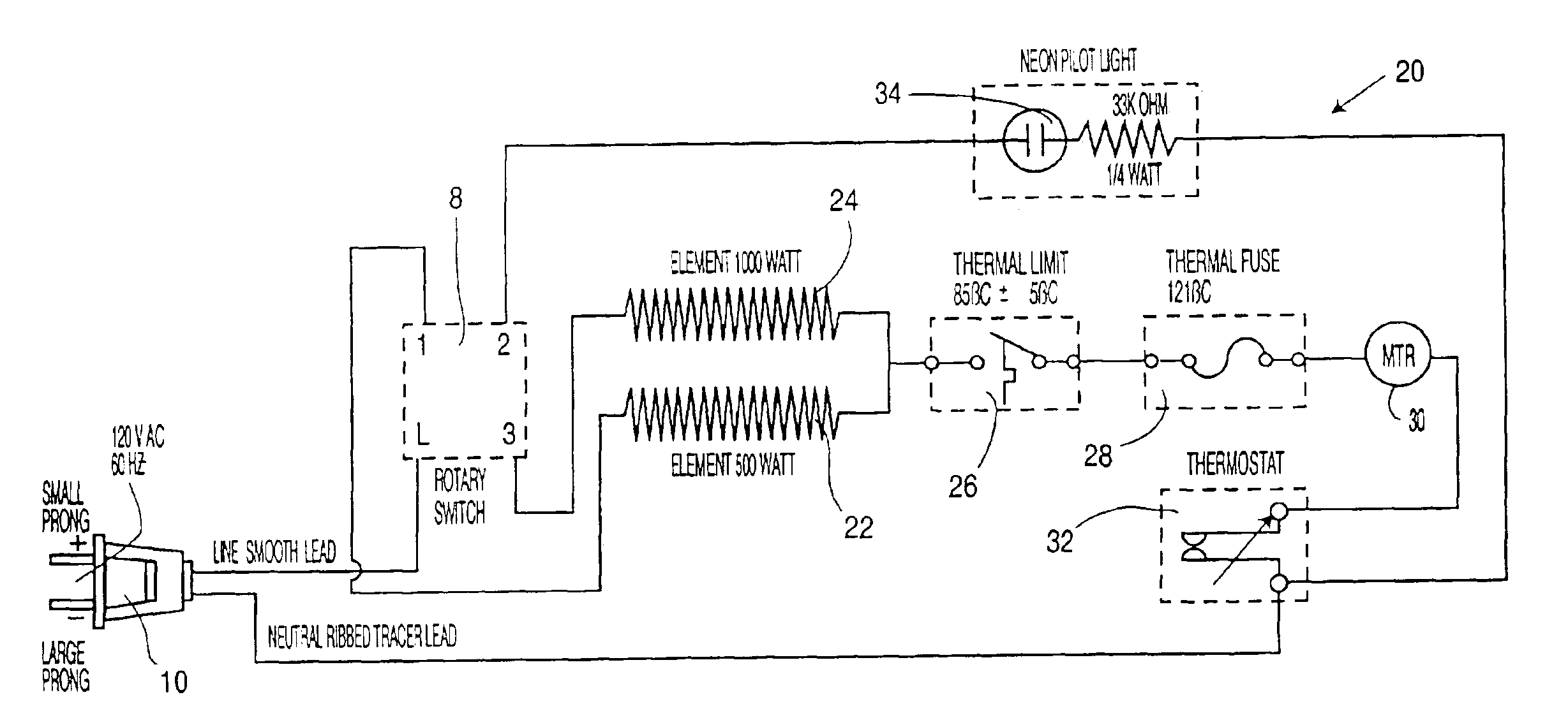
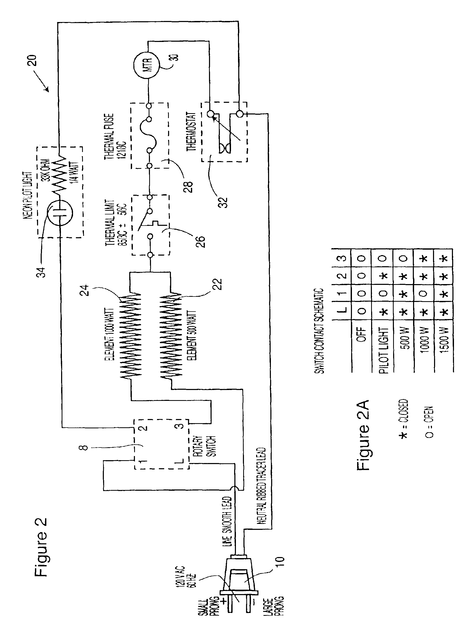
[0029]The preferred heating circuit 20 of FIG. 2 includes the electrical plug 10, a rotary switch 8, a first heating element 22, a second heating element 24, an automatic resetting thermal limit switch 26, a thermal fuse 28, and a fan motor 30 in series with the heating elements 22 and 24. A variable thermostat 32 controls the cutout for a desired temperature selected by the user. The circuit also includes the pilot light 34.

[0030]The multi-position switch 8 of FIG. 2 selectively connects the heating elements 22 and 24 to the electrical plug 10 as indicated in the table 2A. In a first position of the rotary switch, the 500 watt heating element 22 is connected in series with the fan motor 30. Wi...


PUM


Abstract

A heater effectively uses a current controlled fan motor in series with a resistance heating arrangement. The fan motor preferably is wound with a gauge of wire to appropriate for the relatively high current provided to the fan motor. This arrangement is effectively used to adjust the fan speed to match the heat output when the heating arrangement has variable heat output. More desirable operating characteristics are achieved without increasing costs and fan motor manufacturing savings are realized. The portable heater preferably produces heat at different outputs and the current used to power the resistance heating arrangement is used to power the fan motor.

Description

[0001]This is a continuation of application Ser. No. 09 / 965,845, filed Oct. 1, 2000, now U.S. Pat. No. 6,624,397.FIELD OF THE INVENTION[0002]The present invention relates to electrical circuits for heaters and in particular, relates to the heating circuit of a heater where a fan motor is controlled by the current used to power the heating element.BACKGROUND OF THE INVENTION[0003]Portable heaters are commonly used to provide supplemental heat for a localized area or space to improve the comfort level. There are many heaters having a metal housing such as baseboard, ceramic, parabolic and oil filled heaters. More recently, flame retardant polymers have been used for plastic housings and a fan provides efficient heat transfer. The use of a fan driven motor to provide a forced airflow across the heating elements allows the size of the portable heater to be reduced relative to portable heaters that operate on a natural convection cycle. When the elements are activated the fan motor typic...

Claims


Application Information

Patent Timeline
Patent Type & Authority Patents(United States)
IPC IPC(8): F24H9/20F24H3/04H05B3/00
CPCF24H9/2071F24H3/0417F24H15/128F24H15/35F24H15/208F24H15/281F24H15/37F24H15/395
Inventor TATEISHI, ART K.
Owner TATEISHI ART K
Why Eureka
Try Eureka