Direct tympanic drive via a floating filament assembly

a floating filament and drive technology, applied in the field of transducers, can solve the problems of low sound fidelity, ear canal occlusion, acoustic feedback, etc., and achieve the effects of enhancing surface adhesion between the tympanic pad and the tympanic membrane, energy-efficient dynamic coupling, and minimal friction between the coil and the filamen

Inactive Publication Date: 2005-09-06
INSOUND MEDICAL INC
View PDF35 Cites 197 Cited by
  • Summary
  • Abstract
  • Description
  • Claims
  • Application Information

AI Technical Summary

Benefits of technology

[0030]In a preferred embodiment of the invention, the vibrational filament assembly comprises a magnetic tip laterally, which is inserted into the air-core of a cylindrical force element comprised of an electromagnetic coil. The coil produces a magnetic field representative of audio signals, thus imparting vibrations on the magnetic filament assembly which subsequently conducts these vibrations to the tympanic membrane via the filament shaft. The electromagnetic coil is positioned concentrically over the magnetic filament assembly for an extremely energy efficient dynamic coupling. However, friction between the coil and the filament is minimal, thus allowing essentially friction-free axial movement for the filament assembly with respect to the stationary coil.
[0031]The filament assembly is coupled to the tympanic membrane via a tympanic contact coupler at its medial end. The tympanic contact coupler is conically-shaped for fitting into the umbo area, also conically-shaped. The tympanic contact coupler of the filament assembly is weakly attached to the umbo area via minimal adhesion forces between the surface of the tympanic contact coupler and the tympanic membrane. In a preferred embodiment, the surface adhesion between the tympanic pad and the tympanic membrane is enhanced by the application of an adhesion agent such as mineral oil or gel. The tympanic contact coupler is articulated with the shaft of the filament assembly via a subminiature ball joint system. The articulation of the tympanic coupler in conjunction with the friction-free axial movement of the filament assembly provides individual adjustment within the ear canal for properly contacting the tympanic membrane and imparting audible vibrations thereto. The dynamic coupling between the filament assembly and the force transducer essentially eliminates static forces on the tympanic membrane, thus offering safe and comfortable wear.
[0032]Since coupling to the tympanic membrane is vibrational rather than acoustic as with conventional hearing aids, acoustic feedback (whistling) is largely eliminated without restoring to a tight occlusive fit in the ear canal. The energy efficiency and non-occlusive design features of the invented hearing device allow for extended wear embodiments not possible with conventional acoustic hearing aids.

Problems solved by technology

Such devices are largely inconspicuous, and thereby tend to alleviate the social stigma and vanity concerns associated with wearing a visible hearing aid, which are considered a significant obstacle to hearing aid use among the hearing impaired population.
Nevertheless, a number of fundamental limitations remain in hearing devices that utilize air-conduction based technology, including problems of (1) frequency, daily device handling, (2) acoustic feedback, (3) ear canal occlusion, and (4) low sound fidelity.
The problem of frequent conventional device handling relates to frequent insertion and removal from the ear canal.
The requirement of frequent handling, particularly with miniature hearing devices, poses a serious challenge to potential users who suffer physical impairment beyond hearing loss because of age or disorders, such as arthritis, tremors, or other neurologic problems.
The need for frequent battery replacement is attributable in large part to the magnitude of energy consumption by conventional air-conduction receivers (speakers).
The problem of acoustic feedback occurs when a portion of the sound output, typically from a receiver (speaker), leaks to the input of the hearing system such as a microphone of a hearing aid.
Such leakage often causes a sustained oscillation which is manifested by “whistling” or “squealing”.
Acoustic feedback is not only annoying to hearing aid users but also interferes with their speech communication.
Whichever acoustic sealing method is used, ear canal occlusion causes an array of occlusion-related side effects.
Occlusion related problems include discomfort, irritation and even pain; moisture building-up in the occluded ear canal; cerumen impaction; and acoustic occlusion effect, Discomfort, irritation and pain may occur from canal abrasion caused by frequent insertion and removal of a tightly fitted hearing device.
Moisture build-up in the occluded ear canal can cause infection in the ear canal as well as damage to the hearing device within.
Another important problem is cerumen impaction (i.e., blockage of the ear canal by earwax) which occurs when ear wax is pushed deeper in the ear canal by the frequent insertion of a hearing device.
Cerumen can also build up on the receiver of the hearing device, thereby causing frequent malfunction.
The occlusion effect is a common acoustic problem caused by the occluding hearing device, manifested by the perception of a person's own-voice (“self-voice”) being loud and unnatural compared to that with the open ear canal.
Low or inadequate sound fidelity is often experienced with air-conduction receivers (speakers), particularly in hearing aid applications where the frequency response is limited to about 5000 Hz.
Disadvantages of middle ear implants include the cost and risk involved in the surgical procedure, and the additional surgery that may be required to repair device malfunctions or to replace an implanted battery.
Similarly, a primary disadvantage of this type of device is the cost and risk of surgery performed on the delicate vibratory structures of the ear.
A major disadvantage with all of the above electromagnetic hearing systems is the inefficiency associated with transducing radiant electromagnetic energy into magnet vibrations, attributable to the relatively small portion of radiant electromagnetic energy produced by the coil that reaches the magnet.
This and other limitations of such devices render the various modes of radiant electromagnetic transconduction impractical for most hearing aid applications.
However, a major disadvantage of the floating mass transducer is the weight of the transducer assembly being positioned directly on the tympanic membrane.
The devices are not only invasive as disclosed, but also pose a considerable risk to the delicate structures of the tympanic membrane from inadvertent movement of the hearing device, which may occur, for example, simply by normal jaw motion.
Many of these prior art devices are either energy inefficient or occlusive to the ear canal which render them impractical for extended wear.
However, device movements within the ear canal or changes in the atmospheric pressure affecting the position of the tympanic membrane, can cause considerable variations in the dynamic coupling and therefore the perceived sound.
The effect of dynamic coupling due to changes in the static coupling is highly undesirable since it necessitates readjustment of the electroacoustic parameters (i.e., volume, frequency response, etc.) whenever changes in the static coupling occur.

Method used


Image

  • Direct tympanic drive via a floating filament assembly
  • Direct tympanic drive via a floating filament assembly
  • Direct tympanic drive via a floating filament assembly

Examples


Embodiment Construction

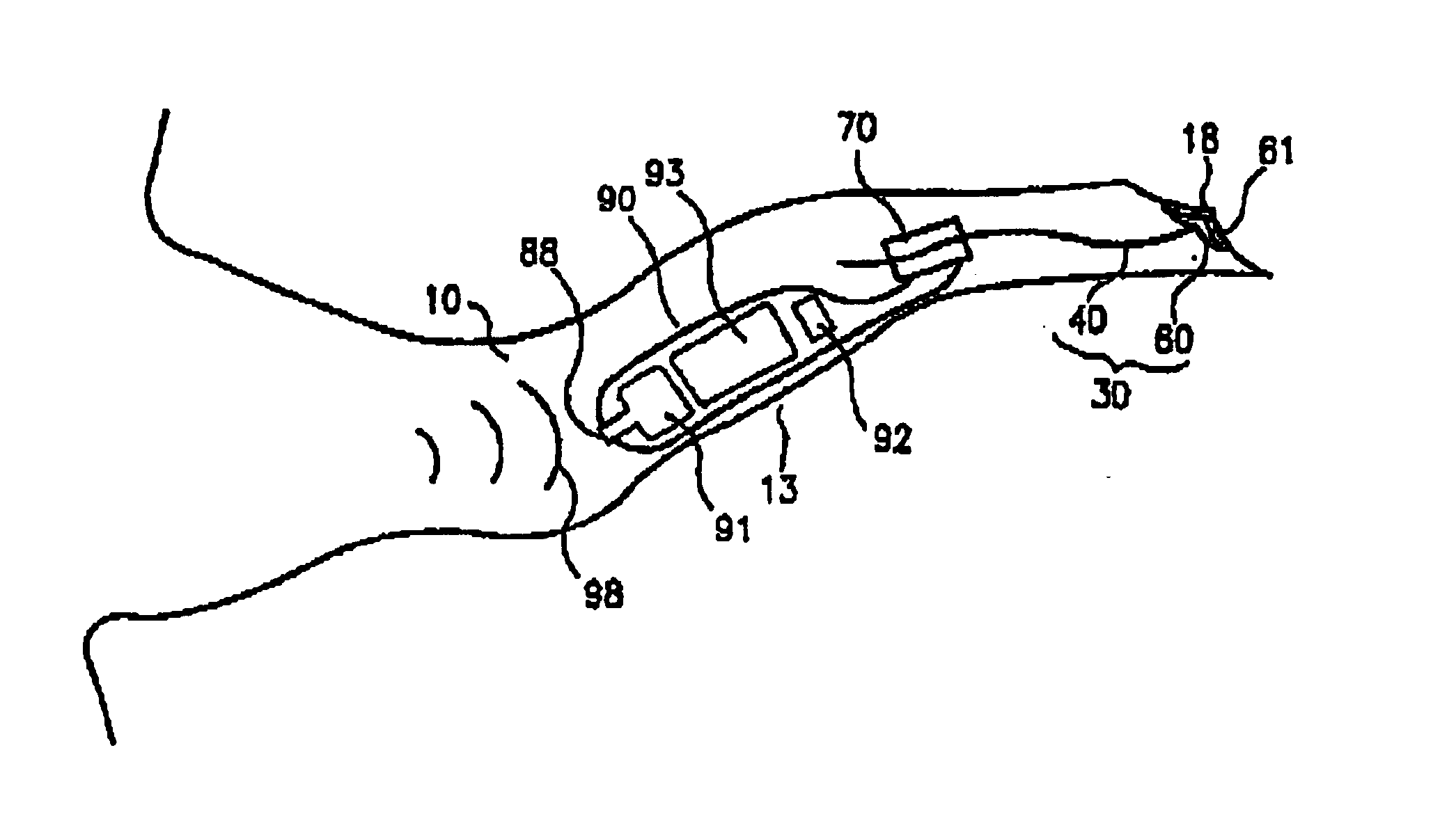
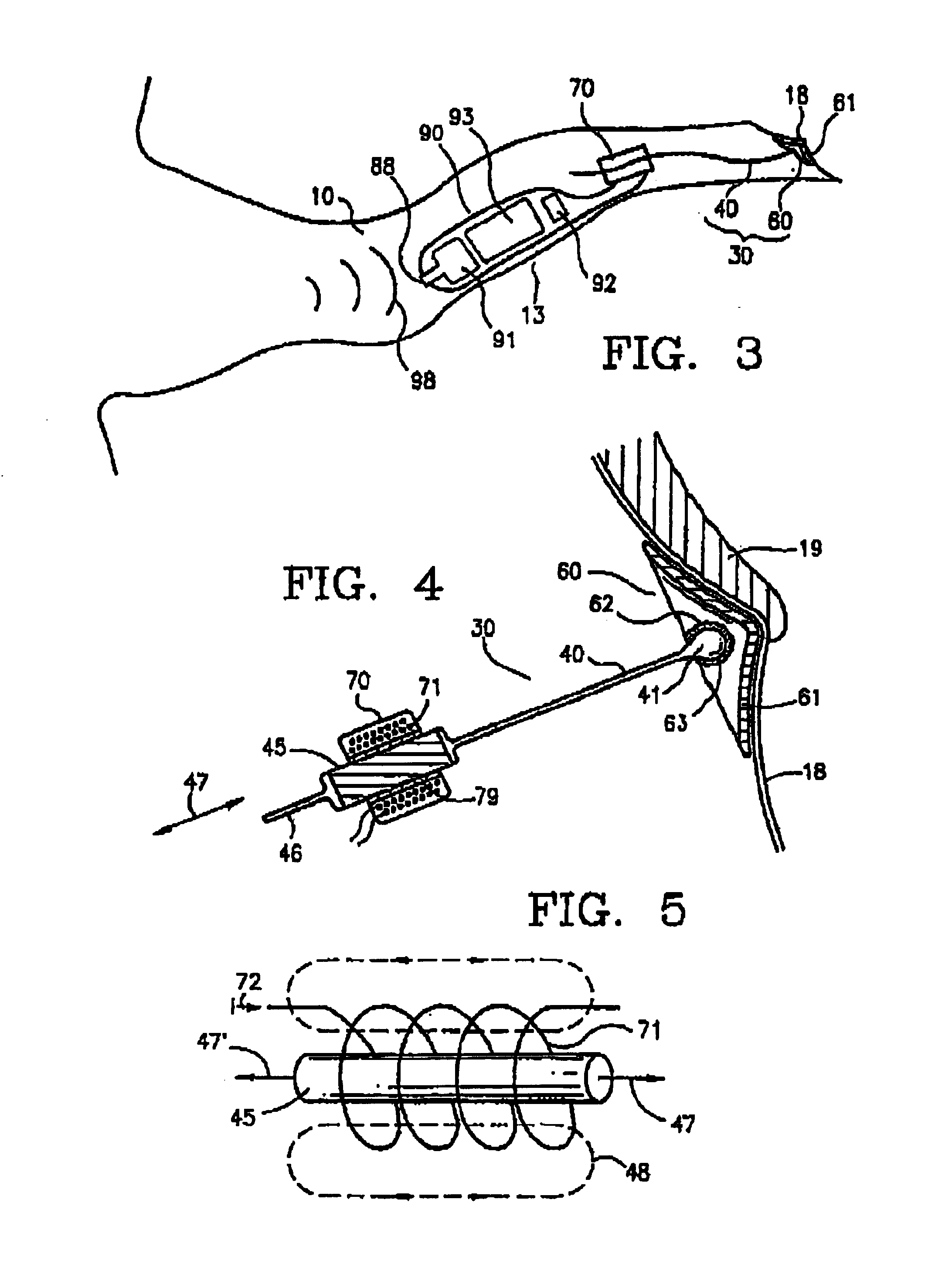
[0065]The present invention, illustrated in FIGS. 3-28, provides a vibrational filament assembly 30 to impart audible vibrations directly onto tympanic membrane 18 (e.g., FIG. 3). The filament assembly 30 consists of a thin elongate vibrational conductive member, referred to as filament shaft 40, and a tympanic coupling element, referred to as tympanic coupling pad 60, placed on the tympanic membrane 18 of a human subject (sometime referred to herein as the wearer of the hearing device, or simply, the wearer). The tympanic coupling pad 60 is weakly adhered to the tympanic membrane and is articulated with respect to the filament shaft 40 to allow for individual variations in the orientation of the tympanic membrane. The filament assembly 30 is dynamically coupled to a vibration force element 70 incorporated within a canal hearing device 90. The dynamic coupling allows the filament assembly 30 to move relatively freely axially with respect to the vibration force element 70 without adv...


PUM

PropertyMeasurementUnit
lengthaaaaaaaaaa
thicknessaaaaaaaaaa
weightsaaaaaaaaaa

Abstract

A canal hearing device has a subminiature filament assembly which vibrates and directly drives the tympanic membrane (eardrum) and imparts audible mechanical vibrations thereto. The filament assembly is partially supported by the tympanic membrane via capillary adhesion thereto and is dynamically coupled to a stationary vibration force element position at a distance from the tympanic membrane within the ear canal. The elongated filament assembly is freely movable within an operable range and is essentially floating with respect to the vibration force element. In a preferred embodiment, the vibrational filament assembly comprises a magnetic section which is insertable into the air-core of an electromagnetic coil. The filament assembly is coupled to the tympanic membrane via an articulated tympanic contact coupler.

Description

CROSS-REFERENCE TO RELATED APPLICATION[0001]This application is related to commonly assigned patent application Ser. No. 09 / 085,486, filed May 27, 1998, titled “Direct Tympanic Membrane Excitation Via Vibrational Conductive Assembly”, referred to herein as “the '486 application”.BACKGROUND OF THE INVENTION[0002]The present invention relates generally to transducers for converting audio signals to audible mechanical vibrations, and more particularly to hearing devices with improved energy efficiency, sound fidelity, and inconspicuous wear.[0003]The external acoustic means (ear canal) is generally narrow and contoured as shown in the coronal view in FIG. 1. The ear canal 10 is approximately 27 mm in length from the canal aperture 17 to the center of the tympanic membrane 19 (eardrum). The lateral part (away from the tympanic membrane) of the ear canal, a cartilaginous region 11, is relatively soft due to the underlying cartilaginous tissue. The cartilaginous region 11 of the ear canal...

Claims


Application Information

Patent Timeline
Patent Type & Authority Patents(United States)
IPC IPC(8): A61F2/18H04R25/00A61L2/16A61F11/00
CPCH04R25/606A61F2002/183H04R25/456H04R2225/023H04R2225/67
Inventor SHENNIB, ADNANSCHINDLER, ROBERTURSO, RICHARD C.
Owner INSOUND MEDICAL INC
Why Eureka
Try Eureka