

Control system for internal combustion engine
a control system and internal combustion engine technology, applied in the direction of electrical control, process and machine control, instruments, etc., can solve the problems of adverse effect on the exhaust characteristics of the engine, the change in the amount of evaporative fuel to be supplied to the intake system, and the change in the amount of exhaust gases to be recirculated to the intake system or the intake system, so as to improve the control accuracy of the air-fuel ratio
- Summary
- Abstract
- Description
- Claims
- Application Information
AI Technical Summary
Benefits of technology
Problems solved by technology
Method used
Image

Examples
first embodiment
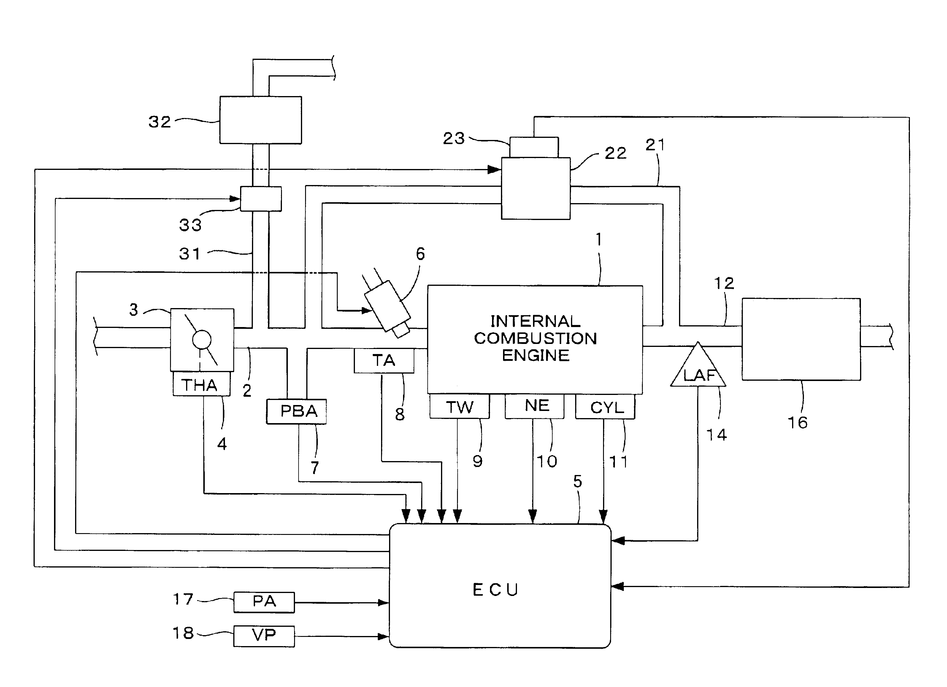
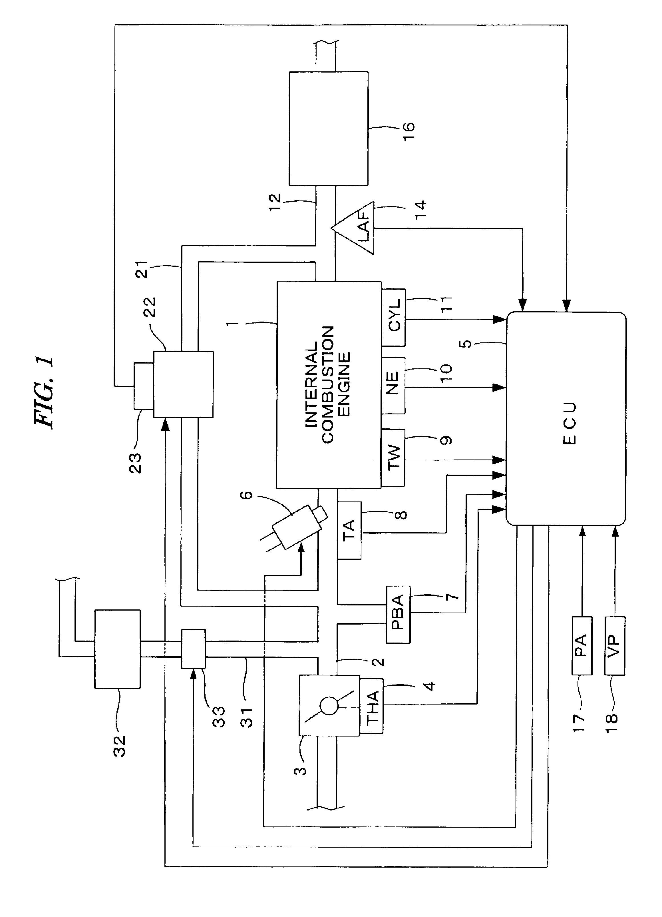
[0033]FIG. 1 illustrates a general configuration of an internal combustion engine (engine) and a control system therefor according to a first embodiment of the present invention. The engine can be a four-cylinder engine 1, for example, having an intake pipe 2 provided with a throttle valve 3. A throttle opening sensor (THA) 4 can be connected to the throttle valve 3, so as to output an electrical signal when the throttle valve 3 opens and supply the electrical signal to an electronic control unit (ECU) 5.
[0034]Fuel injection valves 6, only one of which is shown, are inserted into the intake pipe 2 at locations intermediate between the cylinder block of the engine 1 and the throttle valve 3 and slightly upstream of the respective intake valves (not shown). The fuel injection valves 6 can be connected to a fuel pump (not shown), and electrically connected to the ECU 5. A valve opening period of each fuel injection valve 6 can be controlled by a signal output from the ECU 5.
[0035]An ab...
second embodiment
[0131]FIG. 9 illustrates a schematic diagram showing the configuration of an internal combustion engine and a control system therefor according to a second embodiment of the present invention. In this embodiment, the intake pipe 2 can be provided with an air flow sensor 19 for detecting an intake air flow rate QAIR.
[0132]In this embodiment, the basic fuel injection period TIM can be set according to the intake air flow rate QAIR detected by the air flow sensor 19 so that the air-fuel ratio becomes equal to the stoichiometric ratio. When performing the exhaust gas recirculation, the intake air flow rate QAIR detected by the air flow sensor 19 decreases by an amount corresponding to the exhaust gas recirculation amount QEGR, and the basic fuel injection period TIM can be set according to such a decreased intake air flow rate QAIR. Accordingly, the EGR correction coefficient KEGR is not necessary.
[0133]That is, the fuel injection period TOUT is calculated from Eq. (1a) shown below in t...
PUM
 Abstract
Description
Claims
Application Information