
Transient protection circuit of Darlington amplifier

Active Publication Date: 2005-09-13
SCI COMPONENTS
View PDF5 Cites 1 Cited by
  • Summary
  • Abstract
  • Description
  • Claims
  • Application Information

AI Technical Summary

Benefits of technology

[0020]It is a feature of the invention to provide a Darlington amplifier circuit that prevents destructive transient voltage overshoot conditions from occurring.

Problems solved by technology

Unfortunately, an initial start-up process can result in a dangerous ‘voltage bump’ or overshoot voltage occurring on the transistors of the Darlington amplifier.
In addition to the danger of damaging the Darlington amplifier, the voltage bump can overload and possibly damage the circuitry connected to the output of the Darlington amplifier.
Sequential gain measurements confirm that the amplifier is permanently damaged.
Therefore, the overshoot problem is a pure transient issue at start up.
While various Darlington transistor biasing schemes have previously been used, they have suffered from not being able to adequately protect against destructive transient voltage overshoot conditions and from interfering with normal amplifier operation.

Method used


Image

  • Transient protection circuit of Darlington amplifier
  • Transient protection circuit of Darlington amplifier
  • Transient protection circuit of Darlington amplifier

Examples


Embodiment Construction

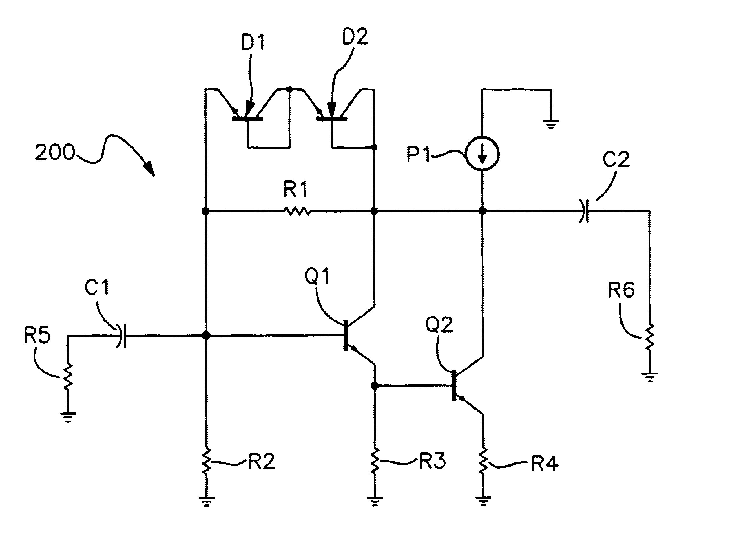
[0062]One possible way to prevent the voltage overshoot problem on transistors Q1 and Q2 is to use a slow power supply at start-up. This solution to use a special power supply is not practical for most applications. In many cases, slow start up is not acceptable from the overall system requirements and restrictions. It is also expensive to design this type of power supply.

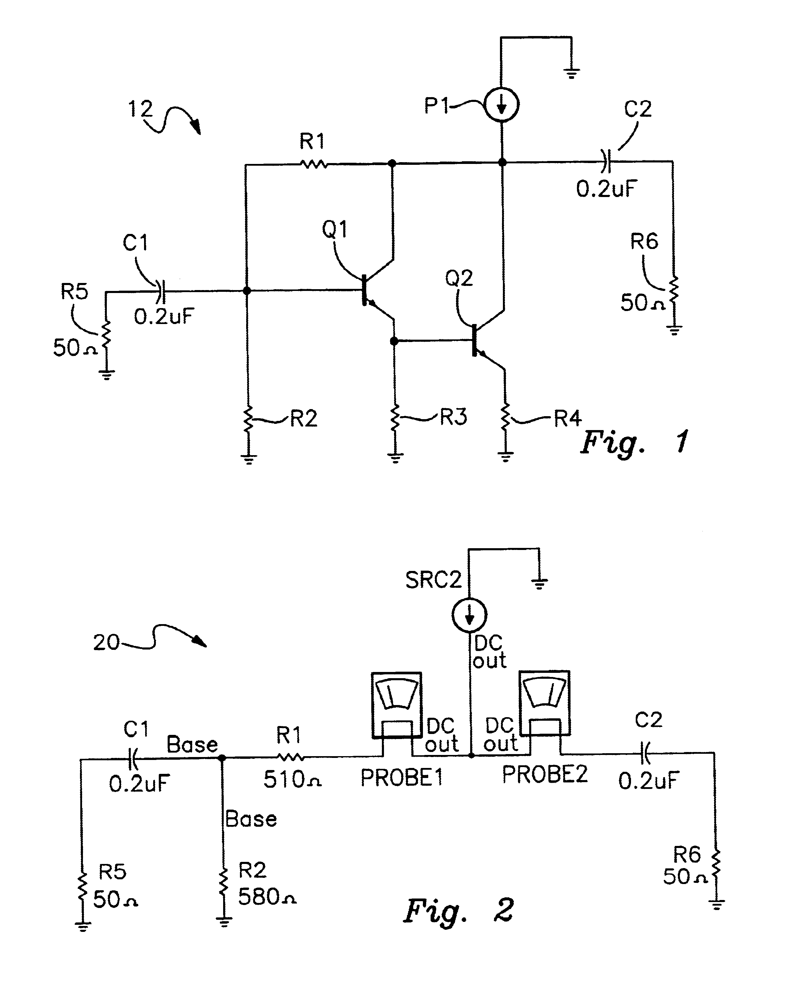
[0063]The voltage overshoot on transistors Q1 and Q2 at start up can be controlled by varying the capacitance ratio of capacitor C2 to C1. The ratio C2 / C1 should be equal or greater than (R1+R5) / R6. This will equalize the time constant of C1*(R1+R5) and C2*R6 and therefore equalize the charging rate of capacitors C1 and C2. For the given example, If the value of C2 is made 5 to 10 times larger than the value of C1, the voltage overshoot on transistors Q1 and Q2 can be prevented.

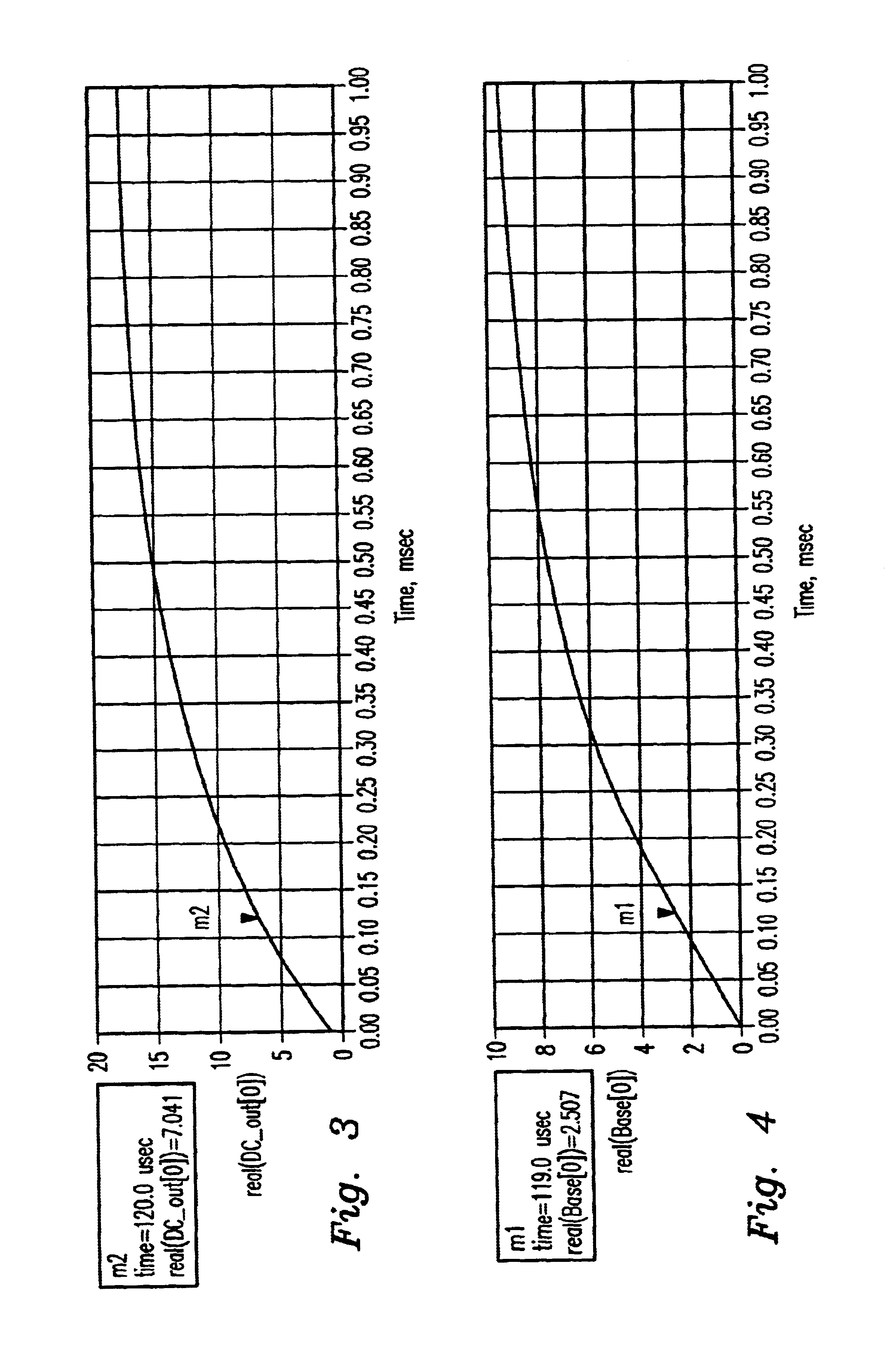
[0064]Referring to FIGS. 14-17, a simulation is shown for circuit 12 of FIG. 1 with the value of capacitor C2 five times larger than C1. FI...


PUM


Abstract

A protection circuit for Darlington amplifiers prevents destructive voltage overshoot conditions from occurring. The Darlington amplifier has a pair of transistors connected in a Darlington configuration. A biasing network is coupled to the transistors for supplying a bias voltage to the transistors. A pair of de-coupling capacitors is coupled to the transistors. One of the de-coupling capacitors is coupled to the input of the Darlington amplifier and the other is coupled to the output. The output capacitor has a larger capacitance than the input capacitor such that excessive voltage is prevented from developing on the transistors.

Description

[0001]This application claims the benefit of provisional application No. 60 / 405,803, filed Aug. 26, 2002.BACKGROUND[0002]1. Field of the Invention[0003]This invention relates to RF and microwave amplifiers in general and more particularly to Darlington gain block amplifiers that have improved biasing to prevent potentially damaging conditions from occurring. The invention also prevents a voltage pulse on the output of the amplifier that is formed during the start-up process, which can damage the circuitry connected to the output of the gain block amplifier.[0004]2. Description of Related Art[0005]Darlington gain block amplifiers are widely used in RF and microwave systems. Darlington amplifiers have a frequency range that starts at DC. The biasing conditions needed by the transistors require de-coupling capacitors at the input and output. The de-coupling capacitors determine the low end of the amplifier frequency range. Normally, Darlington gain block amplifiers receive a DC bias vo...

Claims


Application Information

Patent Timeline
IPC IPC(8): H03F1/52
CPCH03F1/52
Inventor MORDKOVICH, MIKHAIL
Owner SCI COMPONENTS
Features
  • Generate Ideas
  • Intellectual Property
  • Life Sciences
  • Materials
  • Tech Scout
  • Unparalleled Data Quality
  • Higher Quality Content
  • 60% Fewer Hallucinations
Learn More