Metal foil masonry flashings and termination bar therefor

a technology of masonry flashing and metal foil, which is applied in the direction of snow traps, transportation and packaging, chemistry apparatus and processes, etc., can solve the problems of insufficient adhesive quality for rough masonry block surfaces, insufficient pressure-sensitive hot melt adhesive technology needed for peel-and-stick applications, and insufficient filling of pressure-sensitive products, etc., to achieve the effect of enhancing tear and puncture resistan

Inactive Publication Date: 2005-09-20
HOHMANN & BARNARD INC
View PDF14 Cites 31 Cited by
  • Summary
  • Abstract
  • Description
  • Claims
  • Application Information

AI Technical Summary

Benefits of technology

[0031]Other components of the system include a stainless steel drip plate with a hot melt adhesive coating and a termination bar. The drip plate adhesive coating enables the installer to accurately position the plate and, during construction, maintain the alignment thereof. Optionally, a foam layer is placed on the lower surface of the drip plate and on the termination bar so as to improve the sealing of the installation.
[0032]The peel-and-stick technology shown herein enables quick and sure flashing of cavity walls which was unavailable prior to the advances in the materials of both elastomeric membranes and hot melt adhesives. The detailed description of these materials is provided hereinbelow. Preparing surfaces with adhesives and foams enables installation without additional caulking compounds and sealants.OBJECTS AND FEATURES OF THE INVENTION
[0035]It is another object of the present invention to provide in a masonry flashing system for cavity wall construction, combining metal foil and polymeric membrane technologies in system free of bituminous or asphaltic coatings, which flashing resists tearing and puncturing.
[0036]It is yet another object of the present invention to provide labor-saving metal foil masonry flashing system which utilizes peel-and-stick components that are easy and economical to install in cavity wall constructs having a masonry block inner wythe and a brick outer wythe.
[0039]It is another feature of the present invention that the polymeric membrane hereof is highly, ultra-violet resistant and the membrane includes an embedded woven or non-woven fiber layer to enhance tear and puncture resistance.

Problems solved by technology

At that time the technology of pressure-sensitive hot melt adhesives needed for peel-and-stick applications was insufficiently developed.
Some critics indicated that the adhesive quality was insufficient for the rough masonry block surfaces.
Because of the presence of plasticizers, others were apprehensive about the available hot melt adhesives meeting the requisite fire retardancy standards.
However, these filled pressure-sensitive products had disadvantages, such as application problems, phase separation, toxicity, and reduced adhesion upon activation.
While, under ideal circumstances, these peel-and-stick materials were easy to apply, the patent literature indicates that these materials did not conform well to irregular surfaces.
Thus, the prior art bitumens used to secure these flashing materials to masonry walls often lacked the tackiness to bond tightly and durably to the wall surfaces.
On occasion, when circumstances were not ideal, the bitumenous materials drooled marring the aesthetics of the brick veneer.
Although the rubberized asphalt virtually eliminated the possibility of non-adhered areas, the Copper Aqua Flash membrane still had some of the previously described disadvantages of a bitumen-based flashing system.
Despite these early efforts, developing the right combination of materials and methods for flashing cavity walls in a fast and efficient manner has proved elusive.
In addition to the above described technical problems, because there is frequently a delay in erecting the inner wythe and the outer wythe, the flashing installed in the inner wythe is often exposed to substantial ultra-violet radiation.
Here, in situ construction is both labor intensive and requires special equipment for installation.

Method used


Image

  • Metal foil masonry flashings and termination bar therefor
  • Metal foil masonry flashings and termination bar therefor
  • Metal foil masonry flashings and termination bar therefor

Examples


Embodiment Construction

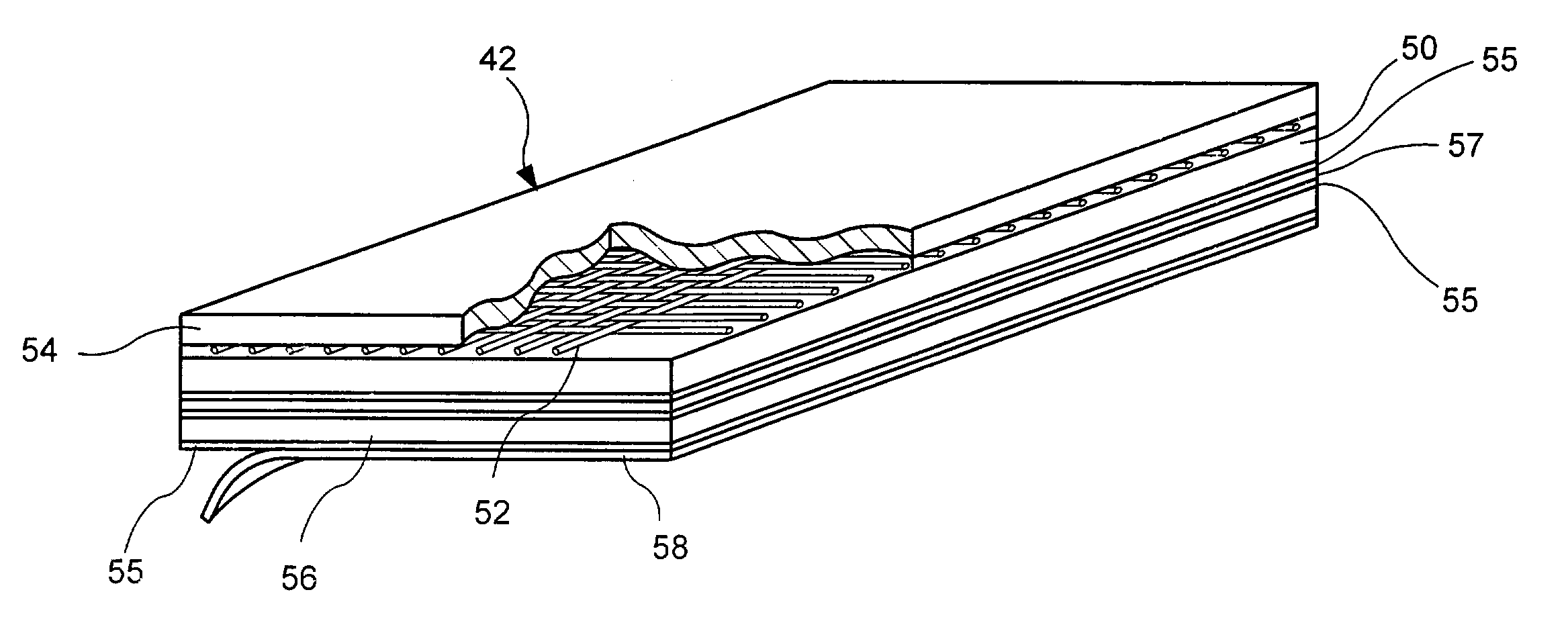
[0053]In the metal foil masonry flashing system of this invention, in contradistinction to the parent case, hot melt adhesives are used to attach polymeric flashing material to at least one side of the metal foil and to the cavity face of the masonry inner wythe. The masonry flashing is emplaced behind the insulation which, in turn, serves to protect against thermal losses, to reduce sound, and to prevent water vapor condensing on colder surfaces. The metal foil increases the longevity of the flashing by enhancing the tensile strength and by improving tear and puncture resistance.

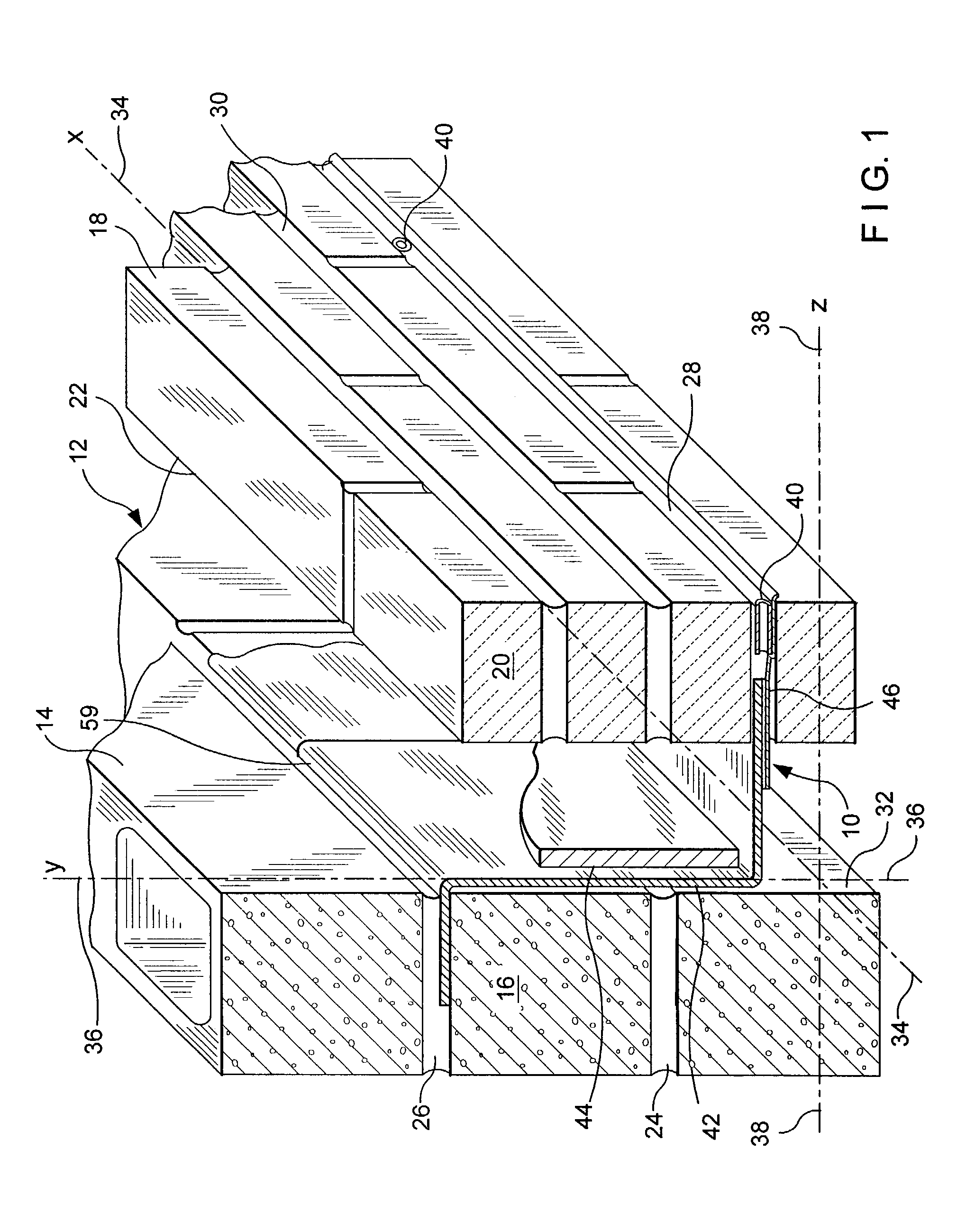
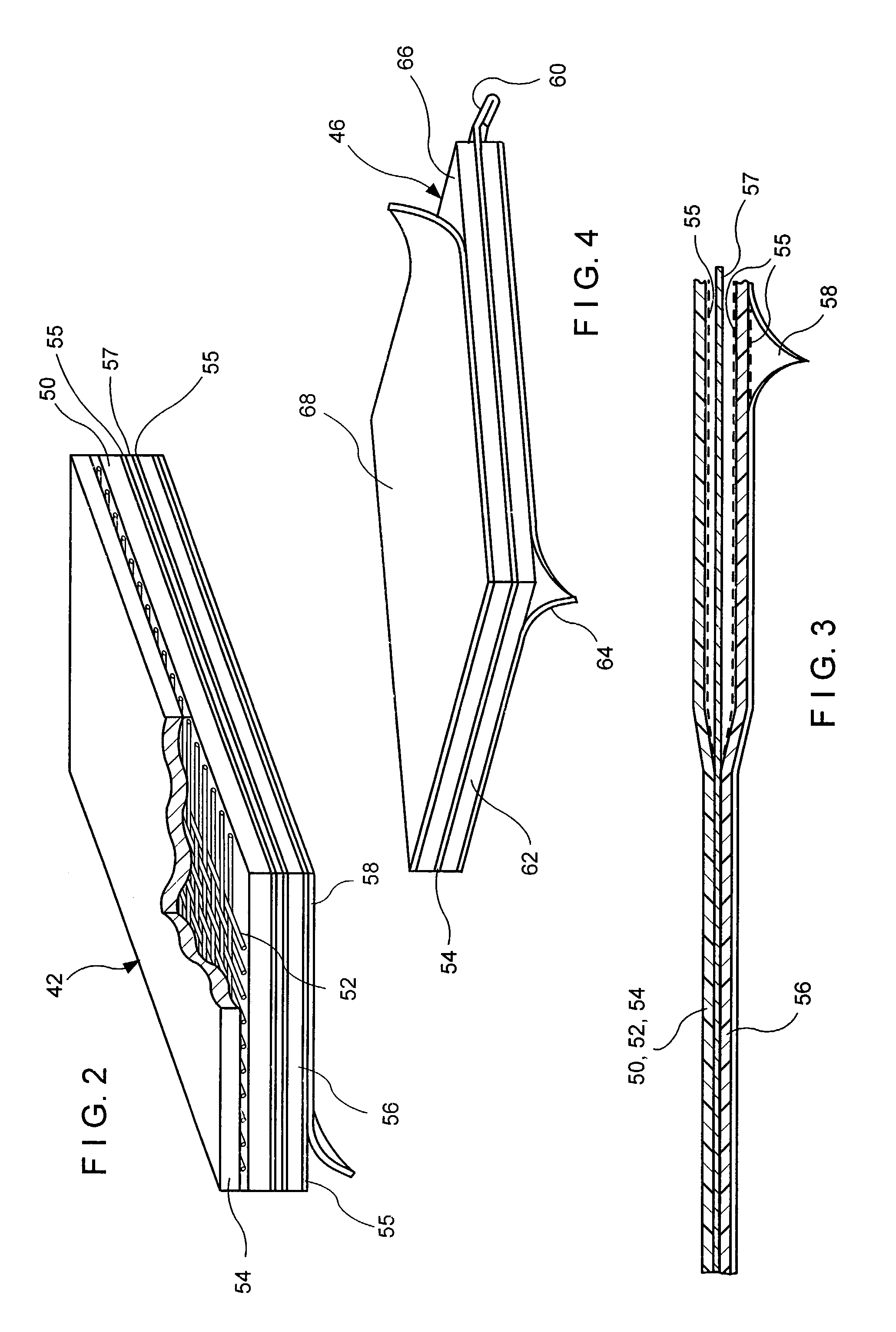
[0054]Referring now to FIGS. 1 through 4, the first embodiment of this invention in which a masonry flashing system, referred to generally by the reference designator 10, is shown. In this embodiment, a cavity wall structure 12 is shown having an inner wythe 14 of masonry blocks 16 and an outer wythe 18 of facing brick 20. Between the inner wythe 14 and the outer wythe 18, a cavity 22 is formed. Successive ...


PUM

PropertyMeasurementUnit
weightaaaaaaaaaa
pressureaaaaaaaaaa
elastomericaaaaaaaaaa

Abstract

A metal-foil-containing flashing laminate is disclosed which laminate is for flashing cavity walls. The laminate has at least one layer of an elastomeric composite over which is placed a hot melt adhesive layer, a metal foil lamina, and another hot melt adhesive layer. In this embodiment the metal foil is encapsulated by the adhesive layers. In application this laminate used with a release paper forms a peel-and-stick product and is suitable for surface mounting. Also to the basic laminate an additional elastomeric composite layer is placed above the metal foil lamina sandwiching the foil and forming a through-wall mountable product. A termination bar for use with surface mounted flashing with a polymeric foam coating is also disclosed. The peel-and-stick flashing may be lap-mounted at the seams between adjacent strips without caulks or sealants.

Description

RELATED APPLICATION[0001]This application is a continuation-in-part of a patent application entitled Masonry Flashing System bearing Ser. No. 10 / 143,484 and filed May 10, 2002 now U.S. Pat. No. 6,584,746.BACKGROUND OF THE INVENTION[0002]1. Field of the Invention[0003]This invention relates to an improved flashing system for cavity wall structures, and more specifically to metal foil masonry flashings and a termination bar therefor.[0004]2. Description of the Prior Art[0005]In the past, investigations relating to cavity wall flashing systems for brick veneer masonry construction have been conducted. While strides have been made in flashing-related technologies, including metal foils, elastomeric materials and hot melt adhesives, there still remain several areas where continued development is ongoing.[0006]The inventors' patents and their assignee's product line are all related to accessories for cavity wall structures and include insulation, and anchoring and seismic devices, and are...

Claims


Application Information

Patent Timeline
Patent Type & Authority Patents(United States)
IPC IPC(8): B32B25/10B32B25/00E04B1/70
CPCB32B25/10E04B1/70E04B1/7046Y10T428/249933Y10T428/249939Y10T428/24994
Inventor HOHMANN, RONALD P.HOHMANN, JR., RONALD P
Owner HOHMANN & BARNARD INC
Why Eureka
Try Eureka