Four-cycle engine

a four-cycle engine and engine technology, applied in the direction of machines/engines, jet propulsion mounting, transportation and packaging, etc., can solve the problems of limiting the enhancement of time-consuming machining and manufacturing of these features, and more difficult to machine these parts of the engine, so as to improve the working precision of related parts

Inactive Publication Date: 2005-09-27
HONDA MOTOR CO LTD
View PDF9 Cites 9 Cited by
  • Summary
  • Abstract
  • Description
  • Claims
  • Application Information

AI Technical Summary

Benefits of technology

[0007]The present invention overcomes several shortcomings associated with the background art and achieves other advantages not realized by the background art. The present inventors have determined that since intake and exhaust valves are provided at a predetermined angle in the above-described cylinder head for a four-cycle engine, the holes for these valves are formed by machining provided with a plurality of different working shafts. Therefore, the machining and manufacture of these features is time consuming, cumbersome and limits the enhancement of the working precision of related parts.
[0008]Similarly, if the head cover joint is inclined and the working axes of the intake valve and the exhaust valve are not uniform, it is even more difficult to machine these pieces of the engine. Therefore, the present inventors have determined that it would be beneficial to reduce the complexity of the manufacturing steps required to construct an inclined head cover joint.
[0012]Since the head cover joint is inclined toward the cylinder joint, the cylinder head can be reduced in size and the weight of the entire engine can be reduced. Since the axes of the intake and exhaust valves, the insertion hole of the ignition plug, or the joint axis of the part are perpendicular to the head cover joint, a machining axis for these parts having such an axis can be made perpendicular to the head cover joint, e.g., thereby improving machining precision and facilitating manufacture. If the head cover joint is inclined downward from the side of the intake port toward the side of the exhaust port, space can be secured over the intake port of the cylinder head. Then, as the engine hanger can be integrated in a position in the vicinity of the cylinder head cover joint utilizing the space, the engine support span is extended and stable support is enabled. In addition, a degree of the freedom of an engine hanger formed position can be enhanced. If the valve train is the SOHC type, a part without a camshaft of the cylinder head cover is lowered and the weight of the cylinder head cover can be reduced.

Problems solved by technology

Therefore, the machining and manufacture of these features is time consuming, cumbersome and limits the enhancement of the working precision of related parts.
Similarly, if the head cover joint is inclined and the working axes of the intake valve and the exhaust valve are not uniform, it is even more difficult to machine these pieces of the engine.
This location is similar to a position over the intake port at the upper end of the rear of the cylinder head, however, this location part has no spare space since the intake port is formed therein.

Method used


Image

  • Four-cycle engine
  • Four-cycle engine
  • Four-cycle engine

Examples


Embodiment Construction

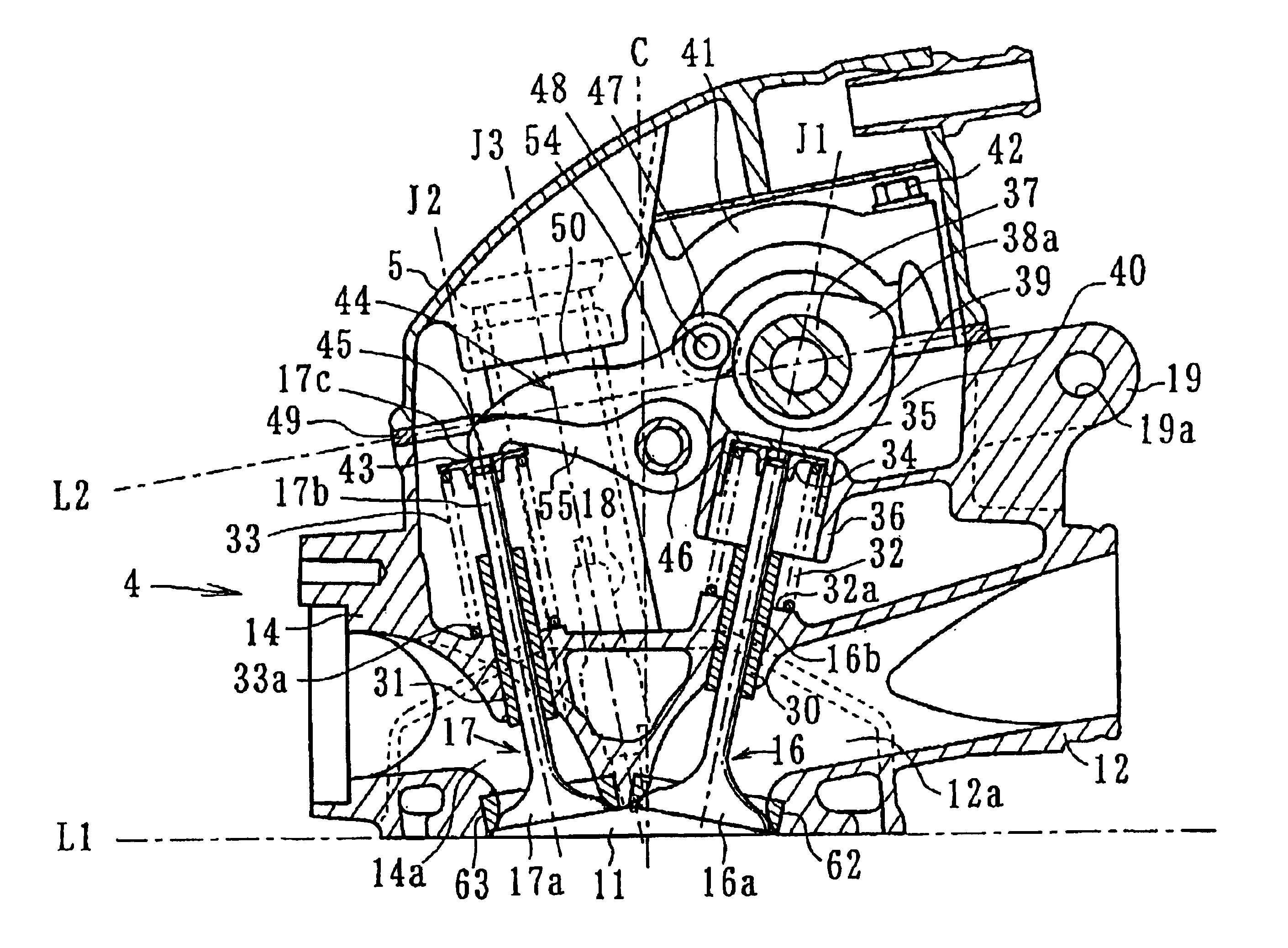
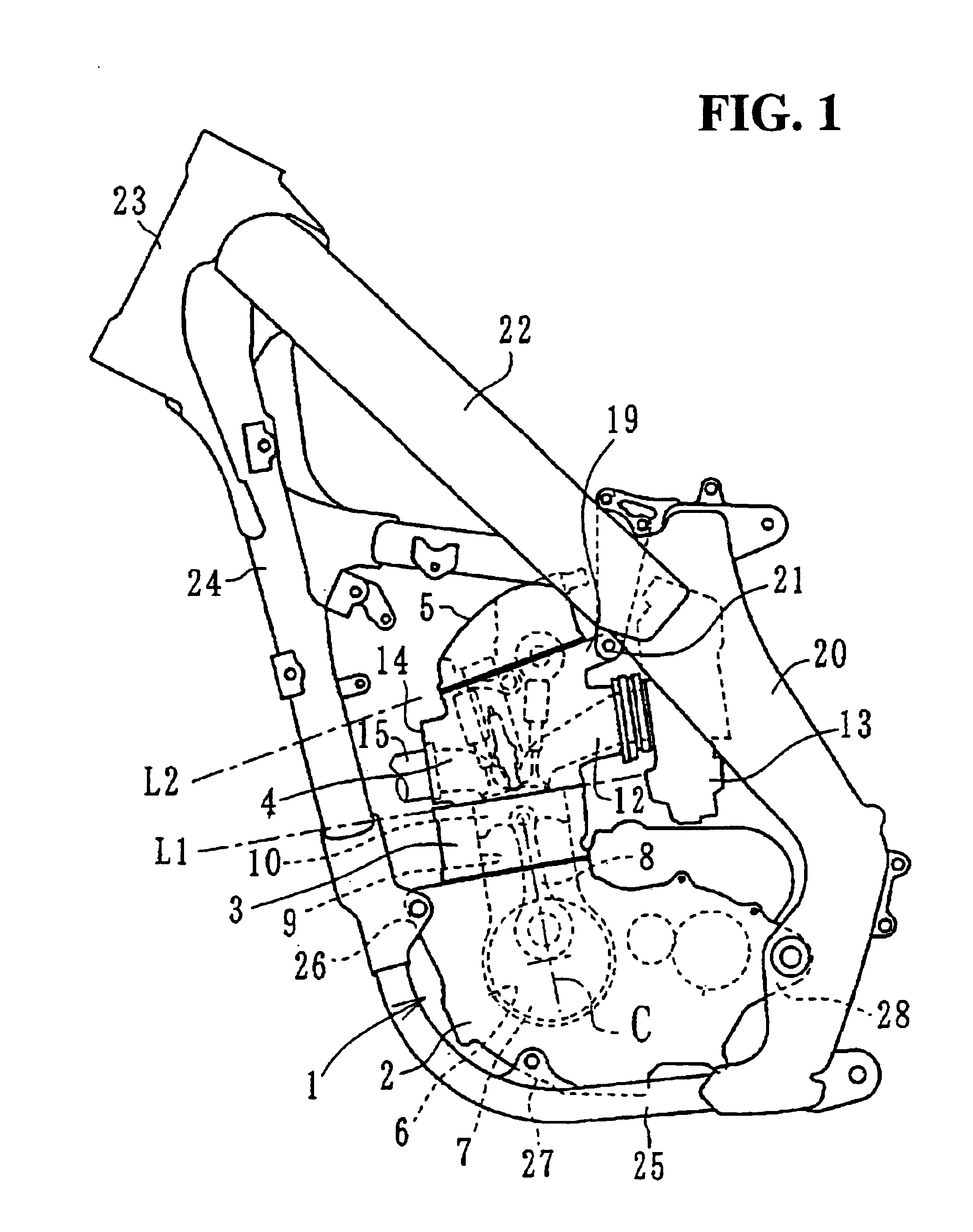
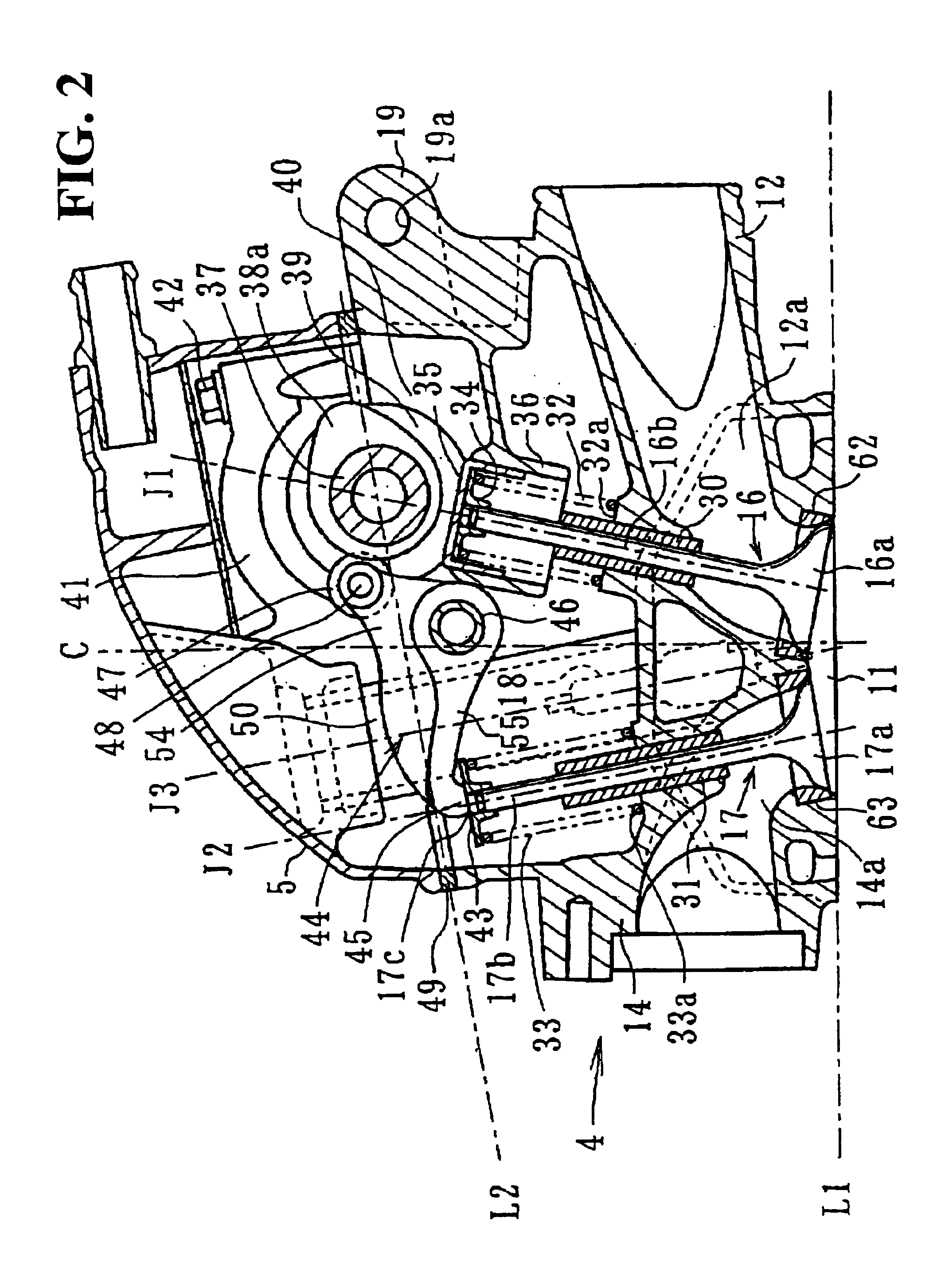
[0022]The present invention will hereinafter be described with reference to the accompanying drawings. FIG. 1 is a side view of an engine mounted to a body frame according to an embodiment of the present invention. FIG. 2 is a side sectional view showing an upper part of the engine of FIG. 1. FIG. 3 is a cylinder head and a valve train viewed along a direction shown by an arrow Y in FIG. 4. FIG. 4 is a side sectional view showing a cylinder head according to an embodiment of the present invention. FIG. 5 is a plan view of an upper face of the cylinder head viewed along a direction shown by the arrow Y in FIG. 4. FIG. 6 is a side view of the cylinder head viewed along a direction shown by an arrow Z in FIG. 4.

[0023]Referring to the drawings, a preferred embodiment will be described in greater detail hereinafter. As shown in FIG. 1, the engine 1 is a water-cooled, single-cylinder four-cycle engine for a motorcycle. A crankcase 2, a cylinder block 3, a cylinder head 4 and a cylinder he...


PUM


Abstract

A cylinder block, a cylinder head and a cylinder head cover are stacked in order to form a four-cycle engine. A valve train of a single overhead camshaft (SOHC) type provided with an intake valve and an exhaust valve is provided in the cylinder head. A line extending parallel with a joint between the cylinder head and the cylinder head cover is inclined forward and downward toward a line parallel with a joint between the cylinder block and the cylinder head. An axis of an exhaust valve and / or an axis of a plug tube is / are perpendicular to the line extending parallel with the joint between the cylinder head and the cylinder head cover. A cylinder head hanger is integrally formed at an uppermost end of a rear portion of the cylinder head over an intake port.

Description

CROSS-REFERENCES TO RELATED APPLICATIONS[0001]This nonprovisional application claims priority under 35 U.S.C. § 119(a) on Patent Application No. 2002-267178 filed in Japan on Sep. 12, 2002, the entirety of which is herein incorporated by reference.BACKGROUND OF THE INVENTION[0002]1. Field of the Invention[0003]The present invention relates to a four-cycle engine used for a vehicle such as a motorcycle, and more particularly to a joint structure for a cylinder head and a cylinder head cover of a four-cycle engine for a vehicle.[0004]2. Description of the Background Art[0005]A conventional four-cycle engine of the background art includes a double overhead camshaft (DOHC) having an intake valve and an exhaust valve driven by different camshafts. Japanese published unexamined patent application No. Hei1-132485, e.g., pp. 9 and 10, and FIGS. 4 and 5 of this document; and Japanese published unexamined patent application No. Hei9-287464, e.g., 0021 (identifier), and FIG. 2 of this document...

Claims


Application Information

Patent Timeline
Patent Type & Authority Patents(United States)
IPC IPC(8): F01L1/26F02F1/38F02B61/00F01L1/18F02B61/02F02F1/26F02B75/02F02F1/24F02F1/00F02F7/00
CPCF01L1/022F01L1/181F01L1/26F02B61/02F02F1/38F01L2105/00F02B2075/027F02B2275/20F01L2305/00
Inventor TSUTSUMI, KOICHITAKAMATSU, HIDETOSHIKOBAYASHI, ITOKOABE, RYUICHI
Owner HONDA MOTOR CO LTD
Why Eureka
Try Eureka