Rapid manufacturing of carbon nanotube composite structures

a carbon nanotube and composite structure technology, applied in the direction of nanostructure manufacturing, conductive materials, metal-working apparatuses, etc., can solve the problems of carbon nanotube composites that are often difficult to produce, application of non-optimal composites for host systems, fractures, wear,

Inactive Publication Date: 2005-09-27
LOCKHEED MARTIN CORP
View PDF11 Cites 56 Cited by
  • Summary
  • Abstract
  • Description
  • Claims
  • Application Information

AI Technical Summary

Benefits of technology

[0016]A technical advantage of the present invention provides for the nodes containing carbon nanotubes that are arranged with respect to each other, illustratively in a similar manner to that of building blocks, to define a free-form structure without the need of a mold or machining or other post-processing operations. The system, based on a template, controls the size, dimensioning, tolerancing, and material make-up of the resulting free-form structure as it deposits and arranges the multiplicity of composite nodal elements. In one exemplary embodiment, the fibers formed of carbon nanotubes comprise reinforcement fibers for strengthening the matrix and overall free-form structure illustratively in a similar manner to that of reinforced concrete. It should be also added that in one exemplary embodiment, the matrix includes a metal. Moreover, in one exemplary embodiment, the matrix includes a metal alloy. In another exemplary embodiment, the matrix includes an intermetallic compound. In another exemplary embodiment, the matrix includes a ceramic. In another exemplary embodiment, the matrix includes a polymer. Those of ordinary skill in the art will readily recognize any combination of matrix materials for combination with the carbon nanotube fibers.
[0017]Another technical advantage includes a program executed t...

Problems solved by technology

Because of their low density, carbon nanotube composites are often difficult to produce when combined with a denser metal, ceramic or polymer matrix.
Moreover, due to their electrostatic characteristics, carbon nanotubes tend to conglomerate with one another during the composite formation process rather than homogeneously disbursing with matrix composite materials.
The tendency for the non-homogeneous formation of carbon nanotubes within a composite matrix often results in the application of a non-optimal composite for use by a host system.
Accordingly, subjecting such non-optimized composite components to various physical factors over time can result in fractures, fatigue, wear, and possibly, catastrophic failure of that component.
Furthermore, the application of post-processing procedures to non-optimized carbon nanotube composites also increases the possibility of a catastrophic failure.
For example, machining and other finishing processes impose unnecessary forces and conditions on such composites that can possibly damage the overall matrix arrangement.
Although composites that include carbon nanotubes homogenously dispersed throughout a metal/ceramic/polymer matrix possess certain technical advantages, including favorable physical properties among others, methods for producing these composites have serious limitations.
As such, it is very difficult, costly, and time consuming to create a composite where carbon nanotubes are homogeneously dispersed throughout a matrix.
Many conve...

Method used


Image

  • Rapid manufacturing of carbon nanotube composite structures
  • Rapid manufacturing of carbon nanotube composite structures
  • Rapid manufacturing of carbon nanotube composite structures

Examples


Embodiment Construction

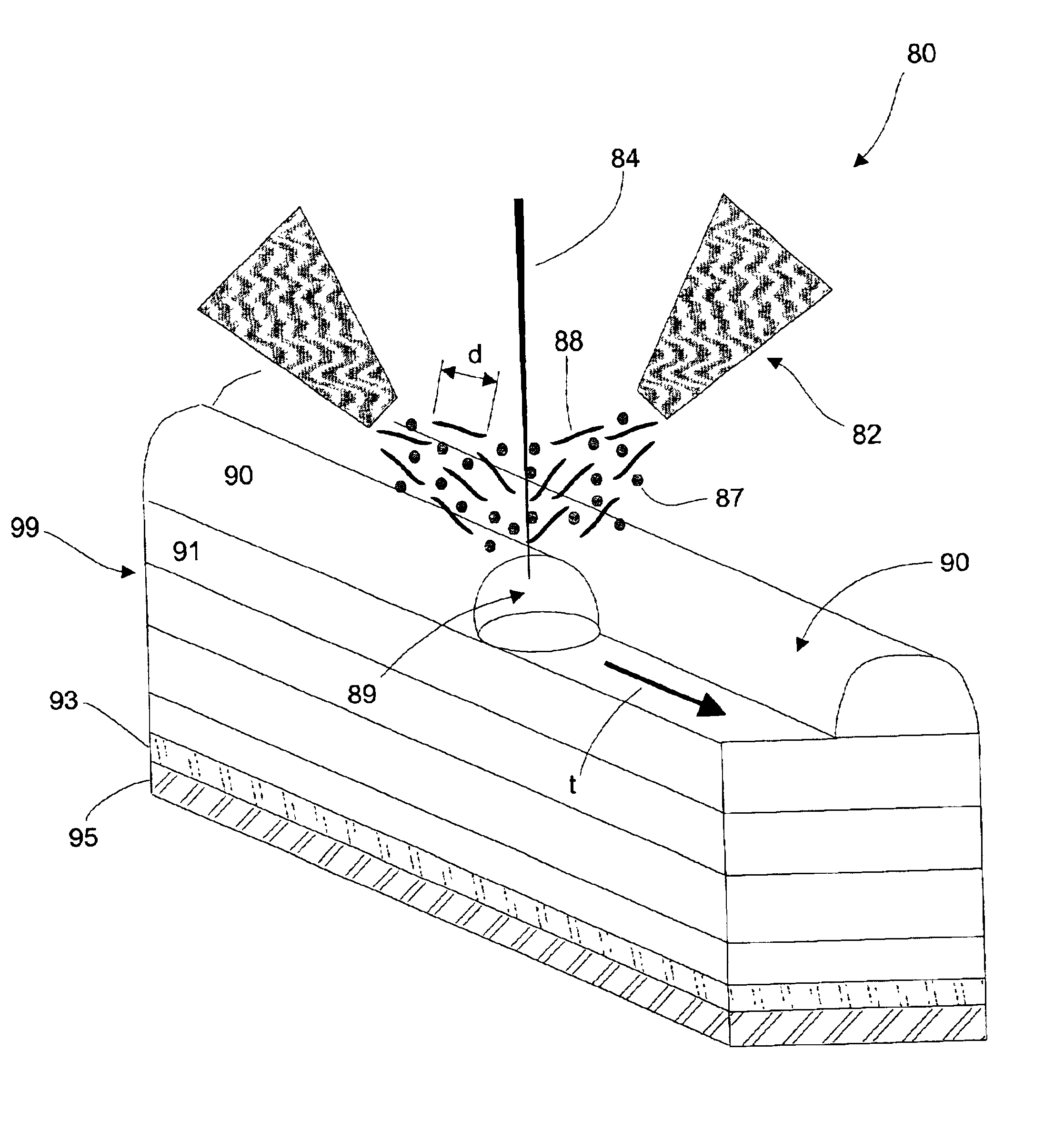
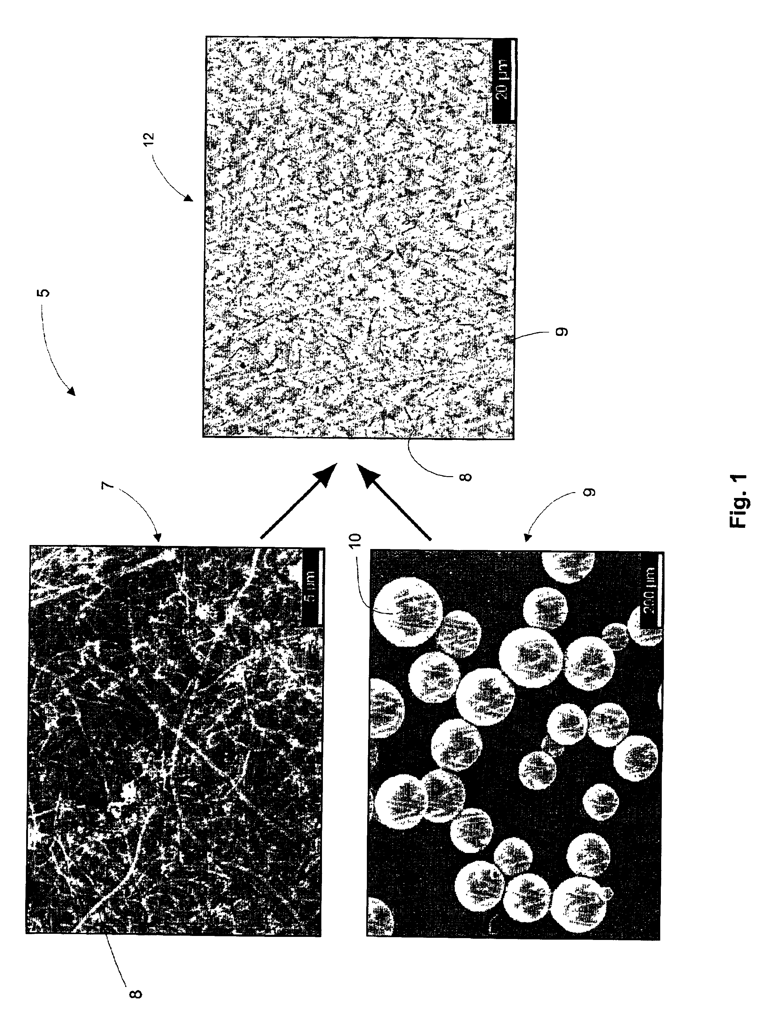
[0035]Preferred embodiments of the present invention are illustrated in the Figures, like numerals being used to refer to like and corresponding parts of the various drawings. FIG. 1 illustrates one aspect, among others, of a process 5 for combining carbon nanotubes 7 with a matrix 9 to produce a composite 12. In another aspect of the present invention shown in FIG. 5, by discretely forming the composite 12 into composite nodal elements 89, a free-form structure 99 is created, via the process 5, by arranging one composite nodal element 89 with respect to another. In effect, composite nodal elements act as “building blocks” that define a free-form structure.

[0036]In one exemplary embodiment, as shown in FIG. 1, carbon nanotube fibers 8 are dispersed between a matrix material 10 provided by the matrix 9 to reinforce the overall free-form structure. By analogizing with reinforced concrete, for example, the carbon nanotube fibers 8 are analogous to reinforcing materials such as steel wh...


PUM

PropertyMeasurementUnit
Lengthaaaaaaaaaa
Lengthaaaaaaaaaa
Structureaaaaaaaaaa

Abstract

A system for fabricating a free form structure of a composite material including carbon nanotubes. The system includes a discharge assembly and a composite formation device operatively linked with the discharge assembly. The discharge assembly dispenses a fusing agent such as for example a high energy density emission, a laser emission or a particle beam emission. The composite formation device includes a composite generator and an arranger in operative engagement with a composite generator. The composite generator engages with the fusing agent so as to create a composite nodal element. The composite nodal element includes a matrix and a multiplicity of fibers formed of carbon nanotubes dispersed throughout the matrix. The arranger positions one node relative to another to define the free form structure.

Description

[0001]This application claims priority of U.S. Provisional Application Ser. No. 60 / 245,916, filed Nov. 3, 2000 entitled “Carbon Nanotube and Metal / Ceramic / Polymer Matrix Composites Produced Through Direct Manufacturing and Netshaped Manufacturing Methods,” which is incorporated herein by reference in its entirety.BACKGROUND OF THE INVENTION[0002]I. Field of the Invention[0003]The present invention generally relates to the creation of free-form composite structures with rapid manufacturing techniques. More particularly, the invention relates to a system and method for fabricating a free-form structure by arranging one composite nodal element relative to another. More particularly, it further relates to generating a composite nodal element containing a matrix and a multiplicity of discreet fibers formed of carbon nanotubes dispersed throughout the matrix.[0004]II. Detailed Description of the Prior Art[0005]Three common allotropes of carbon are diamonds, graphite and fullerenes, such a...

Claims


Application Information

Patent Timeline
IPC IPC(8): B22F3/00B29C70/04B29C70/12B29C70/10B29C70/38C04B35/80C22C49/00C22C49/14C22C1/10B22F1/00
CPCB22F3/008B29C70/12B29C70/305B82Y30/00C22C1/1042C22C49/14C04B35/803Y10T428/12486Y10S977/89Y10T428/2918C22C1/10C22C47/14C22C49/11C22C49/12C22C2026/002B33Y10/00B29C64/153Y10T428/249928Y10T428/249927B33Y30/00B33Y80/00Y02P10/25C04B2235/5288C04B35/117C04B35/80B22F10/28B22F10/30B22F10/25B22F12/70B22F12/22B22F12/88B22F12/53B33Y40/00B33Y70/10B22F1/00B82B3/00B82Y40/00
Inventor BRICE, CRAIG A.HERMAN, FREDERICK J.
Owner LOCKHEED MARTIN CORP
Why Eureka
Try Eureka