Bi-directional optical transceiver module

a transceiver module and bi-directional technology, applied in the field of transceiver modules, can solve the problems of increasing product cost, reducing the service life of the bi-directional optical transceiver module, so as to reduce the loss of light intensity, reduce the cost of product cost, and facilitate manufacturing

Inactive Publication Date: 2005-09-27
SAMSUNG ELECTRONICS CO LTD
View PDF2 Cites 4 Cited by
  • Summary
  • Abstract
  • Description
  • Claims
  • Application Information

AI Technical Summary

Benefits of technology

[0015]In one aspect, the present invention provides a bi-directional optical transceiver modul...

Problems solved by technology

However, the bi-directional optical communication system is not effective in terms of cost and size as the light source and the optical detector are separately constituted.
The conventional bi-directional optical transceiver module suffers great loss in light intensity if the position of the multilayer thin-film filter is less than precisely aligned.
Therefore, either the need for precise alignment means for the multilayer thin-film filter increases produ...

Method used


Image

  • Bi-directional optical transceiver module
  • Bi-directional optical transceiver module
  • Bi-directional optical transceiver module

Examples


Embodiment Construction

[0027]Preferred embodiments of the present invention will be described herein below with reference to the accompanying drawings. The following description omits detailed description of well-known functions or constructions to avoid obscuring the invention in unnecessary detail.

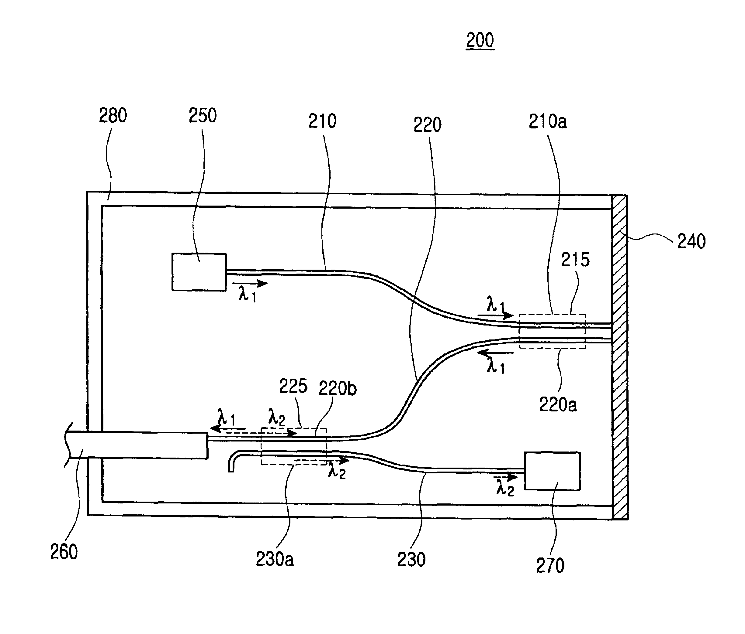
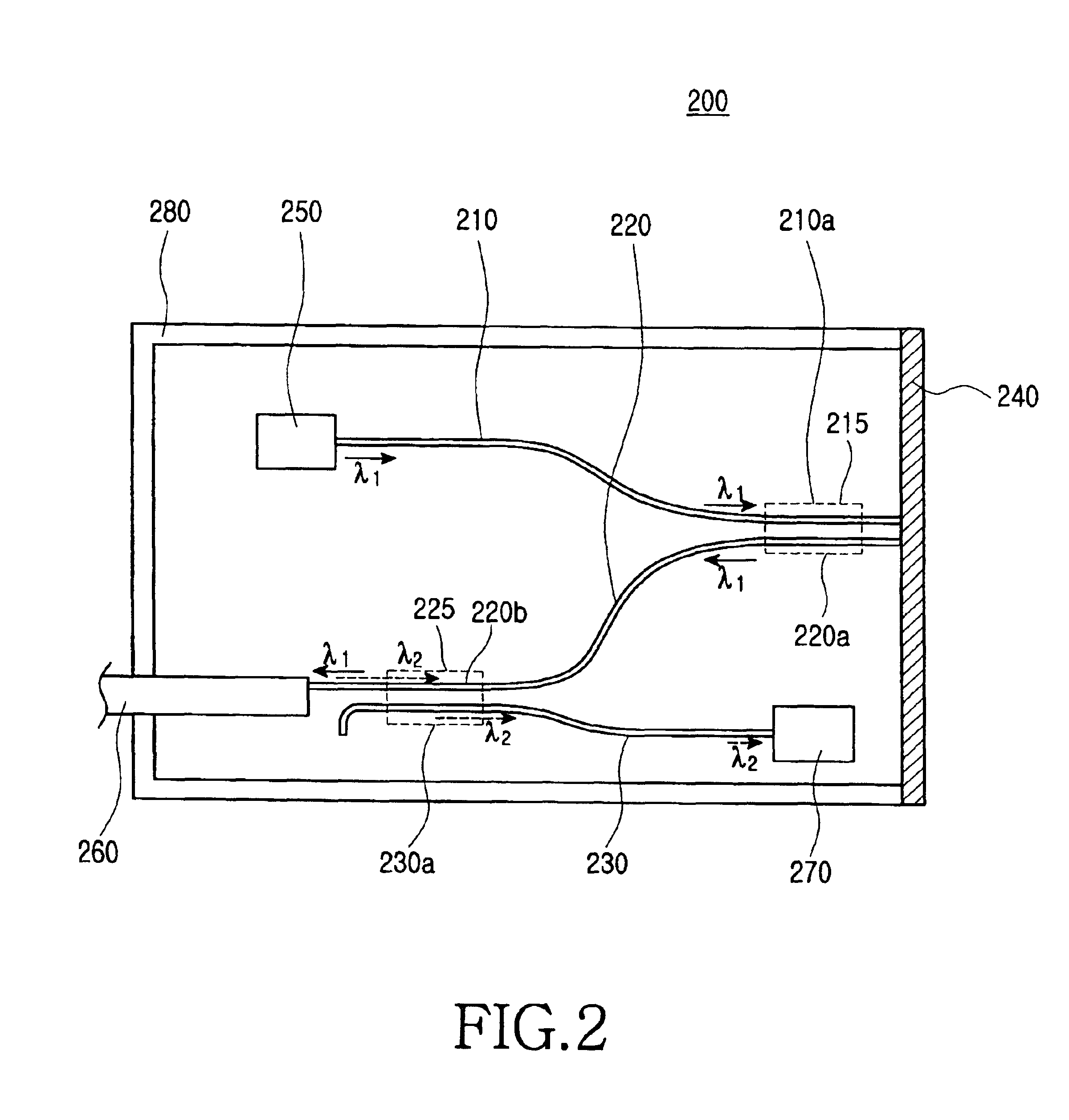
[0028]FIG. 2 illustrates a bi-directional optical transceiver module having first and second mode coupling regions of a directional coupler type and a high reflection layer according to an embodiment of the present invention. The module 200 includes an optical fiber 260, a light source 250, an optical detector 270, a waveguide substrate 280 with a high reflection layer 240 formed in a portion thereof for reflecting a transmission optical signal λ1, a first waveguide 210, a second waveguide 220 for transmitting the transmission optical signal mode-coupled from the first waveguide 210 to the optical fiber 260 and transmitting a reception optical signal λ2, and a third waveguide 230 for transmitting the reception...


PUM


Abstract

In a bi-directional optical transceiver module, a first waveguide transmits a optical signal received from a light source to a high reflection layer formed on a waveguide substrate. A second waveguide extends from the optical fiber to the high reflection layer. With a first mode coupling region formed by ends of the first and second waveguides near the high reflection layer, the second waveguide transmits the transmission optical signal mode-coupled from the first waveguide to the optical fiber and receives the reception optical signal from the optical fiber. A third waveguide extends from the optical detector to near an end of the optical fiber. With a second mode coupling region formed by an end of the third waveguide and the other end of the second waveguide, the third waveguide transmits the reception optical signal mode-coupled from the second waveguide to the optical detector.

Description

CLAIM OF PRIORITY[0001]This application claims priority under 35 U.S.C. § 119 to an application entitled “Bi-directional Optical Transceiver Module,” filed in the Korean Intellectual Property Office on Jun. 4, 2003 and assigned Ser. No. 2003-36056, the contents of which are herein incorporated by reference.BACKGROUND OF THE INVENTION[0002]1. Field of the Invention[0003]The present invention relates generally to a transceiver module, and in particular, to a bi-directional optical transceiver module of a planar optical waveguide type for bi-directional optical transmission and reception.[0004]2. Description of the Related Art[0005]A typical bi-directional optical communication system includes a light source for converting an electrical signal to an optical signal and an optical detector for detecting an external input optical signal. However, the bi-directional optical communication system is not effective in terms of cost and size as the light source and the optical detector are sepa...

Claims


Application Information

Patent Timeline
IPC IPC(8): G02B6/42G02B6/28
CPCG02B6/4246H01S3/0941H01S3/1062H04B10/2589
Inventor LEE, YU-SHEOPRYOO, HYUN-HOMUN, GI-TAEYOON, YOUNG-KWON
Owner SAMSUNG ELECTRONICS CO LTD
Why Eureka
Try Eureka