Parasitic losses are those losses of energy that are attributable to any energy required to facilitate the ternary reactions in the fuel cell.
This need has not been satisfied, however, because of the prohibitive expense associated with such fuel cell systems.
Heretofore known fuel cell assemblies have not shown sufficient reliability and have disadvantageous maintenance issues.
Heretofore known PEM
fuel cells, however, have not been able to efficiently maintain proper
ternary phase distribution.
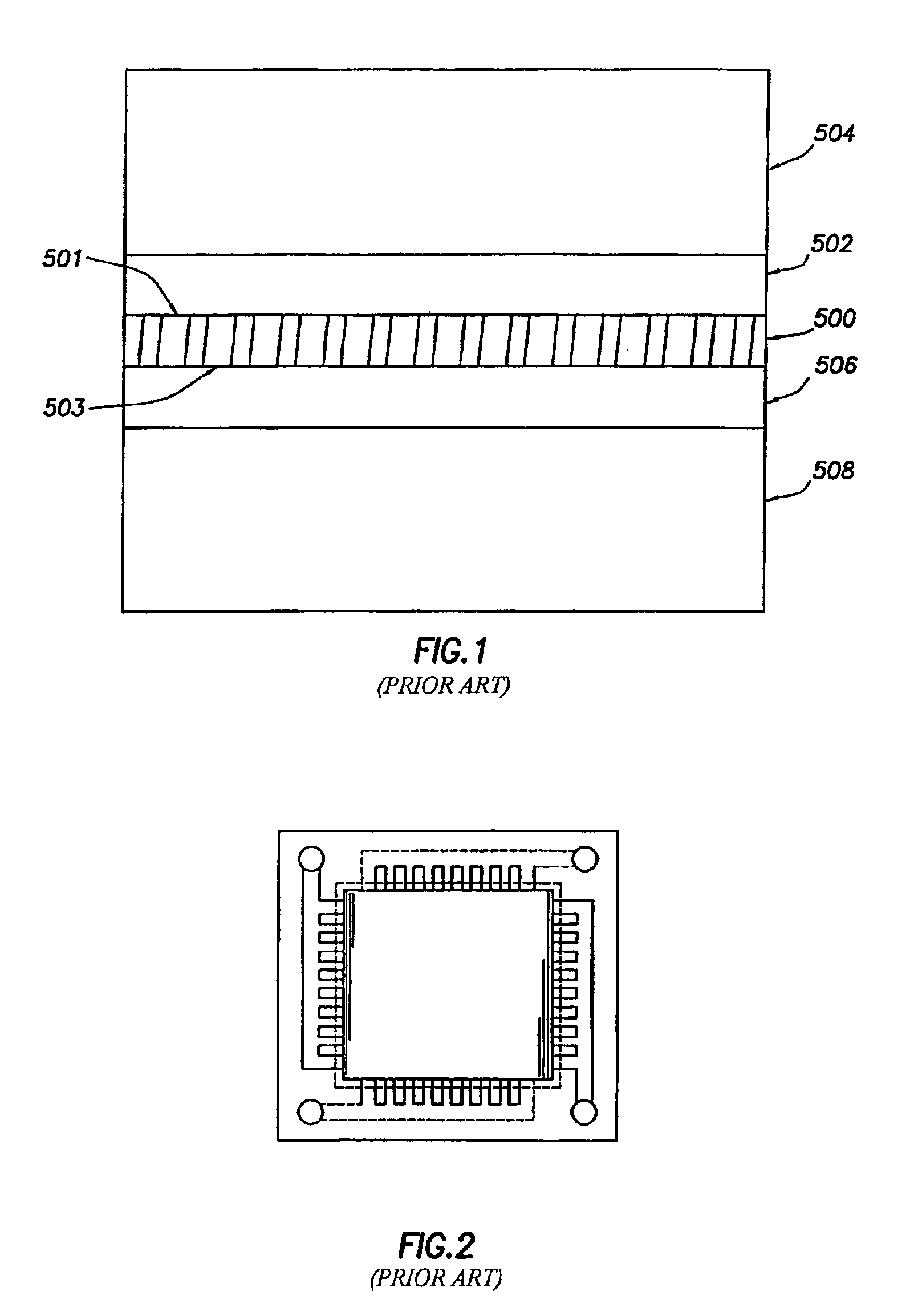
The costs of manufacturing these plates and the associated materials costs are very expensive and have placed constraints on the use of fuel cells in residential and light-commercial applications.
Further, the use of these planar serpentine arrangements to facilitate the flow of the fuel and oxidant through the
anode and
cathode has presented additional operational drawbacks in that they unduly limit
mass transport through the electrodes, and therefore, limit the maximum power achievable by the fuel cell.
One of the most problematic drawbacks of the planar serpentine arrangement in the
anode and
cathode relates to efficiency.
However, when utilizing a conventional serpentine construction, the
anode gas and the
cathode gas are not uniformly disbursed onto the
electrolyte.
This results in a significant decrease in efficiency in the fuel cell.
The second most problematic drawback associated with serpentine arrangements in the electrodes relates to the ternary reactions that take place in the fuel cell itself.
This is particularly problematic in the cathode as both a liquid and a gas are transported simultaneously through the
electrode's serpentine pattern.
These hot spots in the serpentine arrangement unduly and prematurely degrade the catalytic
active layer and supporting membrane.
This pressure differential causes the reactants, especially the fuel, to be fed into the flow fields unevenly, which results in distortions in the flow fields causing hot spots.
This also results in nonuniform
disbursement of the reactants onto the catalytic active
layers.
Ultimately, this conventional method of supplying the necessary fuel and oxidant to a fuel cell results in a very inefficient process.
Conventional PEM fuel stacks often flood the cathode due to
excess water in the cathode gas flow field.
Flooding occurs when water is not removed efficiently from the
system.
Flooding is particularly problematic because it impairs the ability of the reactants to adequately diffuse to the catalytic active
layers.
Insufficient supply of water can dry out the anode side of the PEM membrane
electrolyte, causing a significant rise in stack resistance and reduced membrane durability.
This amount of pressure that must be used to ensure good electrochemical interactions presents many operational difficulties.
For example, if the
voltage of a single fuel
cell assembly in a stack declines significantly or fails, the entire stack must be taken out of service, disassembled, and repaired, resulting in significant repair costs and down-time.
Second, inadequate compressive force can compromise the seals associated with the manifolds and flow fields in the central regions of the interior distribution plates, and also compromise the electrical contact required across the surfaces of the plates and MEAs to provide the serial
electrical connection among the fuel cells that make up the stack.
Third, the extreme compressive force used unduly abrades the surfaces of the fuel cell modules within the stack, resulting in wear of components in the fuel cell assemblies such as the catalyst
layers of the electrolyte, thereby leading to increased losses in fuel cell stack and fuel
cell assembly efficiency.

