
Ultra wide band transmitter

a transmitter and wide band technology, applied in the field of wireless data transmitters, can solve the problems of increasing interference with data reception, poor signal reception, and using conventional narrowband modulated carrier frequencies

Inactive Publication Date: 2005-10-04
INTELLECTUAL VENTURES HLDG 73
View PDF114 Cites 82 Cited by
  • Summary
  • Abstract
  • Description
  • Claims
  • Application Information

AI Technical Summary

Benefits of technology

[0022]The present invention includes a transmitter Medium Access Control (MAC) layer comprising a clock synchronization unit, at least one frequency divider, at least one slot allocation unit, and a multiplexer/demultiplexer. The clock synchronization unit has a timing device with a clock speed. The at least one frequency divider is coupled to the clock synchronization...

Problems solved by technology

There are important disadvantages associated with using conventional narrowband modulated carrier frequencies.
Particularly, in multipath environments such as inside rooms and buildings, data communication degrades because of multipath propagation or fading and can result in poor signal reception.
Further, the rapidly increasing use of wireless consumer products has “crowded the airwaves” and will result in increasing interference with reception of data.
Still further, narrow band modulated carriers rely on use of relatively expensive components such as high-Q filters, precise local high-frequency oscillators, and power amplifiers.
Spread-spectrum signals for digital communications were originally developed and used for military communications either to provide resistance to jamming or to hide the signal by transmitting the signal at low power and, thus, make it difficult for an unintended listener to detect its presence in noise.

Method used


Image

  • Ultra wide band transmitter
  • Ultra wide band transmitter
  • Ultra wide band transmitter

Examples


Embodiment Construction

[0037]Those of ordinary skill in the art will realize that the following description of the present invention is illustrative only and not in any way limiting. Other embodiments of the invention will readily suggest themselves to such skilled persons.

[0038]The present invention provides a Time Division Multiple Access (TDMA) system and method that allows sharing a wireless medium which can identify and operate in a variable bit rate environment. The present invention provides a system and method capable of supporting devices with vastly different bandwidth requirements. Some devices, such as television receivers, require high bandwidth data communication. The higher cost associated with a television allows for the design of a television receiver having high data rate modulation techniques. Other devices such as home thermostats have lower bandwidth requirements and require simpler modulation techniques for lower cost connectivity.

[0039]The present invention operates within a network...

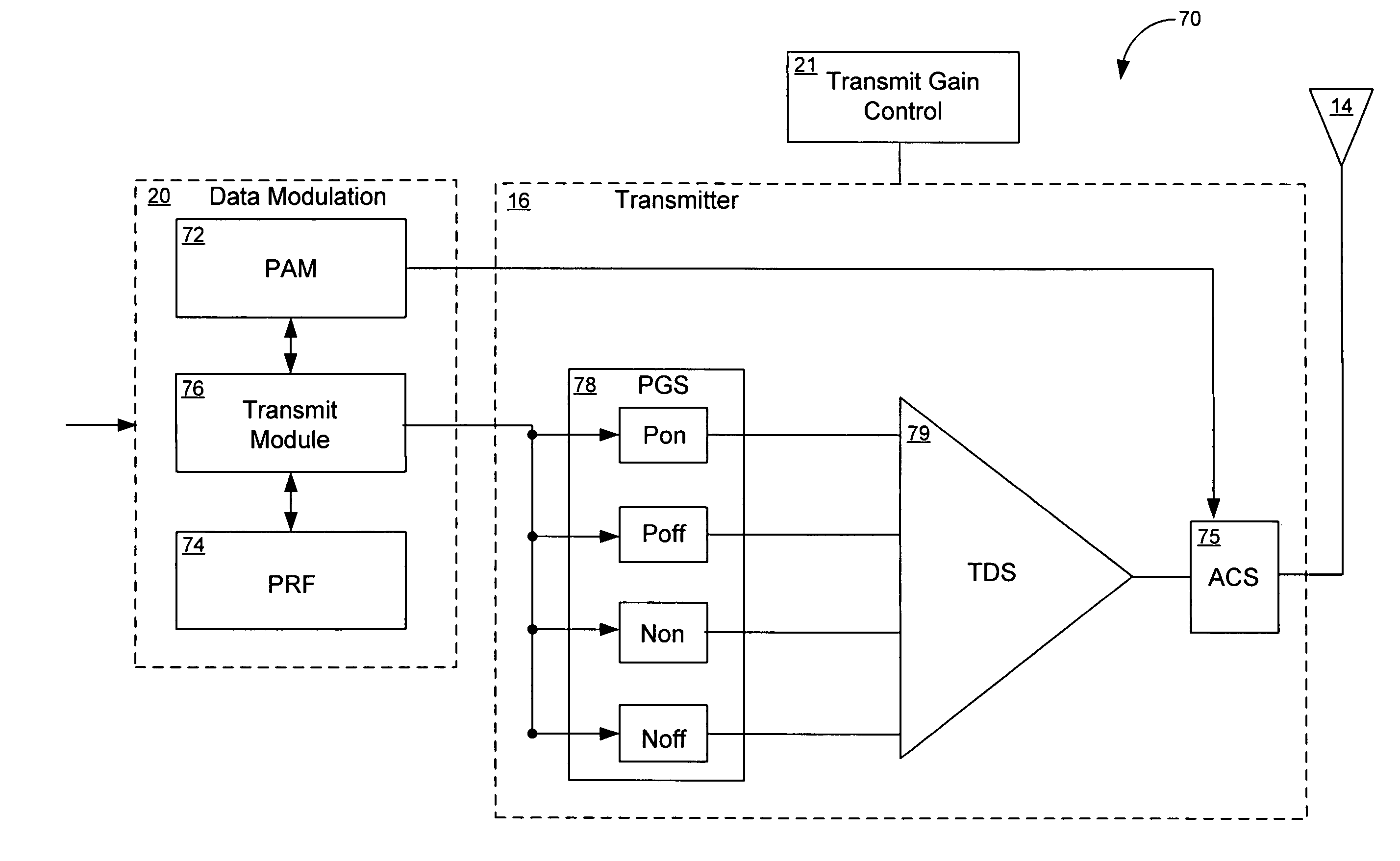
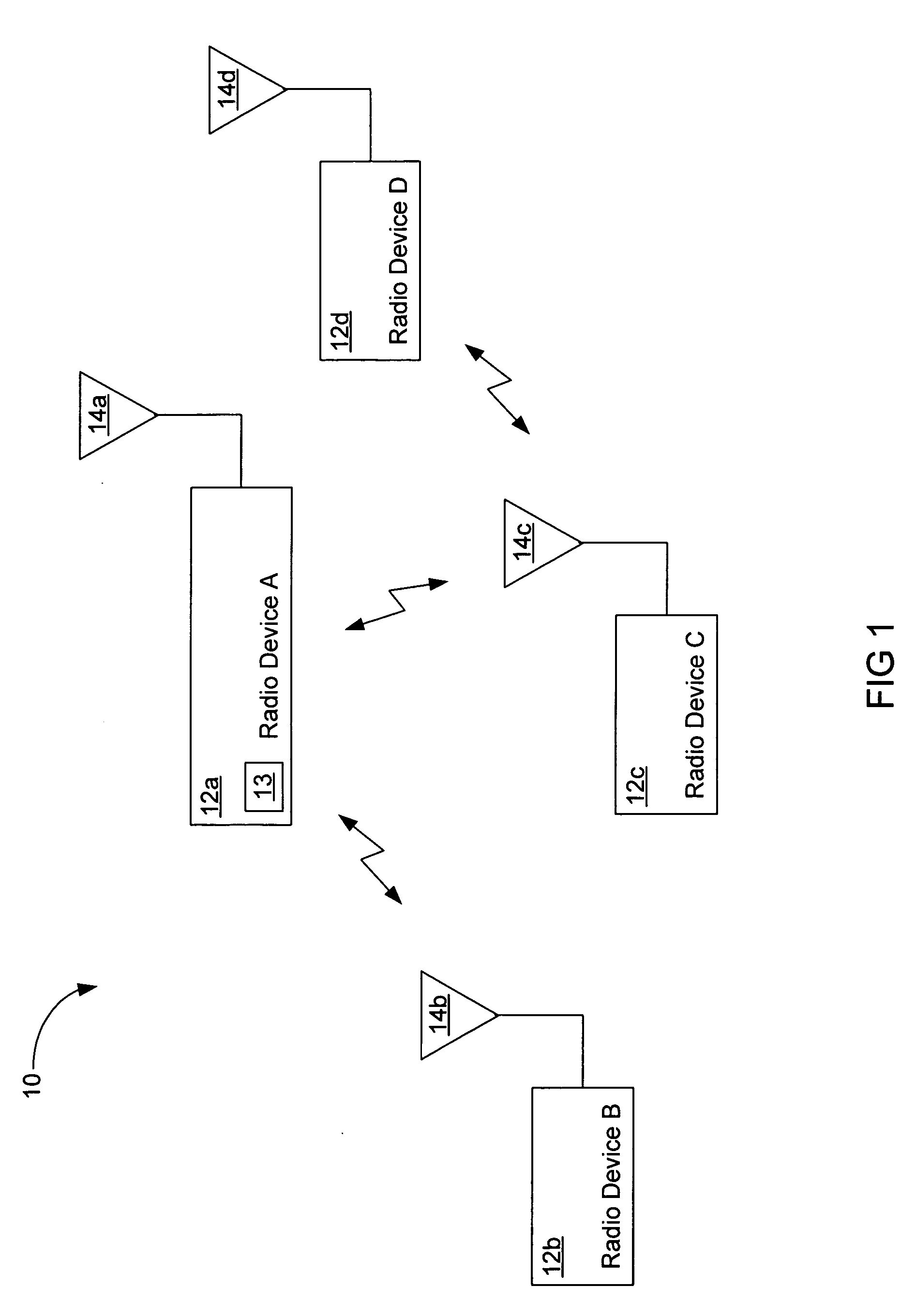
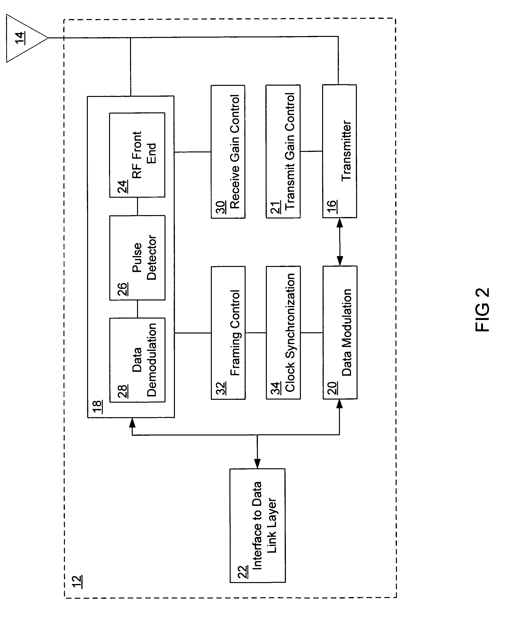

PUM


Abstract

A transmitter system is provided. In one embodiment, the transmitter system includes a data modulation unit, which generates a stream of data that is synchronized with a master clock. The transmitter system additionally includes a transmitter that transmits the stream of synchronized data by way of an attached antenna. In another embodiment the transmitter system includes a Medium Access Control (MAC) layer that includes a clock synchronization device, a frequency divider, a slot allocation unit, and a multiplexer / demultiplexer. This Abstract is provided for the sole purpose of complying with the Abstract requirement rules that allow a reader to quickly ascertain the subject matter of the disclosure contained herein. This Abstract is submitted with the explicit understanding that it will not be used to interpret or to limit the scope or the meaning of the claims.

Description

[0001]This application is a continuation of PCT / US01 / 19908 filed Jun. 21, 2000.BACKGROUND OF THE INVENTION[0002]1. Field of the Invention[0003]This invention pertains generally to a wireless data transmitter. More particularly, the invention relates to an ultra wide band transmitter for transmitting base band signals.[0004]2. The Prior Art[0005]Wireless communication increasingly relies on the transmission of data in digital formats. Typically, a data stream is modulated onto a carrier frequency, and the modulated carrier signal is transmitted over a communications channel from a transmitter to a receiver. Generally, these communication systems use conventional narrow band modulated carriers for wireless network communication.[0006]There are important disadvantages associated with using conventional narrowband modulated carrier frequencies. Particularly, in multipath environments such as inside rooms and buildings, data communication degrades because of multipath propagation or fadi...

Claims


Application Information

Patent Timeline
IPC IPC(8): H04L27/34H04L27/20H04L27/00
CPCH04L27/0008H04L27/2003H04L27/3405H04B2001/6908
Inventor AIELLO, ROBERTOROGERSON, GERALDSPARRELL, CARLTONTUFT, JACOB
Owner INTELLECTUAL VENTURES HLDG 73
Learn More