Compact package design for vertical cavity surface emitting laser array to optical fiber cable connection

a technology of optical fiber cable and laser array, which is applied in the direction of sustainable manufacturing/processing, semiconductor/solid-state device details, instruments, etc., can solve the problems of not meeting the design challenges of high-speed data and telecommunication applications, adding significantly to their cost, and tab bonding that is conventionally used for electrical attachmen

Inactive Publication Date: 2005-10-11
II VI DELAWARE INC
View PDF19 Cites 91 Cited by
  • Summary
  • Abstract
  • Description
  • Claims
  • Application Information

AI Technical Summary

Benefits of technology

[0017]An advantage of the present invention is a technique of interconnecting a VCSEL array with parallel optical fiber ribbon.
[0018]Another advantage of the present invention is a submount that supports a VCSEL array and that employs a vertical-walled housing.
[0019]Another advantage of the present invention is a submount that supports, for example, a VCSEL array and includes an insulating glass slide cover.
[0020]Another advantage of the present invention is a VCSEL array employing a micro inkjet lens array and a multi-layer ceramic housing.
[0021]A opto-electronic housing package according to the principles of the present invention includes a submount having a plurality of conductive traces on a surface, and a plurality of opto-electronic elements attached to the submount. Furthermore, the submount has a plurality of walls extending up from the submount to support a glass slide. Additionally, a plurality of bonding wires electrically connects the individual opto-electronic elements to a plurality of conductive traces on the upper portion.
[0022]An alternative opto-electronic housing package according to the principles of the present invention includes a submount having a plurality of conductive traces on a lower portion, an upper portion over the lower portion, and a plurality of conductive vias that pass through the submount's body. A plurality of opto-electronic elements are attached to the submount with the individual opto-electronic elements electrically connected thorough the lower portion to the conductive vias. Furthermore, bonding wires electrically connect the individual opto-electronic elements to the conductive traces.

Problems solved by technology

While generally successful in serial module applications based on a discrete VCSEL and Photo-Detector (PD), applications with VCSEL arrays and photo detector arrays have many more challenges.
One particular problem is interconnecting VCSEL arrays and / or photo detector arrays with higher-level systems.
To assist electrical attachment, VCSEL / photo detector array substrates are usually relatively large, which adds significantly to their cost.
Furthermore, the tab bonding that is conventionally used for electrical attachment does not meet the design challenges of high-speed data and telecommunication applications.
Such design challenges include well-controlled impedances and low parasitic capacitances.
However, most emerging parallel fiber transceiver implementations for VCSELs use non-standard, non-hermetically sealed packages.
This creates problems for system designers, particularly when high reliability in high temperature, high humidity environments is required.
Optically coupling arrays to paralleled ribbon optical fiber connectors can be very difficult to do in a package that provides good electrical signal integrity, high optical coupling efficiency, and hermiticity.
Such alignment is difficult to achieve, particularly when parallel optical fiber connectors are used.

Method used


Image

  • Compact package design for vertical cavity surface emitting laser array to optical fiber cable connection
  • Compact package design for vertical cavity surface emitting laser array to optical fiber cable connection
  • Compact package design for vertical cavity surface emitting laser array to optical fiber cable connection

Examples


Embodiment Construction

[0043]Reference will now be made in detail to embodiments of the present invention, examples of which are illustrated in the accompanying drawings.

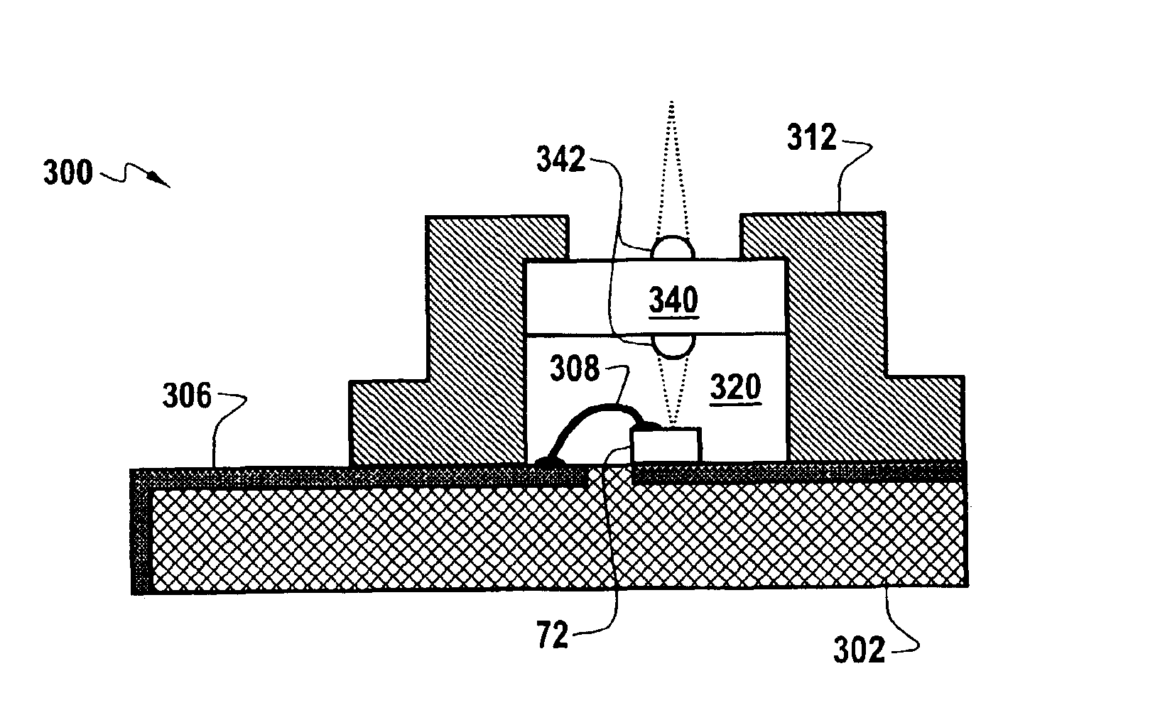
[0044]The principles of the present invention provide for robust opto-electronic device packages that (a) can be hermetically sealed; (b) can be implemented in a TO-like package; (c) can incorporate glass windows on a metal can, (d) can enable robust electrical input-output schemes for operation at 10 G+ data rates, (e) can optically interface with ribbon-type optical fiber connectors, (f) can optically couple to the external environment via mirrors and lenses, (g) can incorporate low-cost, high performance micro-optics, and that (h) can leverage existing die mounting, can-welding, alignment and assembling practices and techniques.

[0045]FIGS. 3 and 4 illustrate a first embodiment opto-electronic device package 300 that is in accord with the principles of the present invention. The first embodiment can include, or be used in, one or more v...


PUM


Abstract

A hermetically sealed, opto-electronic array housing assembly having a ceramic base, electrical connectors, a metal can, and a glass window. The glass window can support a micro-lens array. The metal can receives the glass window. The electrical impedance of the electrical connectors is beneficially carefully controlled to enable high-speed data communications. A multi-element optical fiber connector can provide for optical communications to and/or from an opto-electronic array contained within the housing.

Description

CROSS-REFERENCE TO RELATED APPLICATIONSBACKGROUND OF THE INVENTION[0001]1. Field of the Invention[0002]This invention relates to the packaging of opto-electronic devices and arrays, specifically including vertical cavity surface emitting laser arrays and photo detector arrays, that couple to optical fibers.[0003]2. Discussion of the Related Art[0004]Vertical cavity surface emitting lasers (VCSELs) represent a relatively new class of semiconductor lasers. While there are many variations of VCSELs, one common characteristic is that they emit light perpendicular to a wafer's surface. Advantageously, VCSELs can be formed from a wide range of material systems to produce specific device characteristics. In particular, the various material systems can be tailored to emit different wavelengths, such as 1550 nm, 1310 nm, 850 nm, 670 nm, and so on.[0005]VCSELs include semiconductor active regions, distributed Bragg reflector (DBR) mirrors, current confinement structures, substrates, and conta...

Claims


Application Information

Patent Timeline
Patent Type & Authority Patents(United States)
IPC IPC(8): G02B6/42H05K1/18H05K3/34H05K3/40
CPCG02B6/42G02B6/4249G02B6/4292H05K1/181H05K1/182H05K3/3442H05K3/403H05K2201/10121H05K2201/10446H01L2224/73265H01L2924/3011H01L2924/00H01L2224/48091H01L2224/48227H01L2924/00014G02B6/4251G02B6/426G02B6/4267G02B6/4272H05K1/0274Y02P70/50
Inventor LIU, YUE
Owner II VI DELAWARE INC
Why Eureka
Try Eureka