Stitched LGA connector

a technology of lga connectors and lga strips, which is applied in the direction of elastomeric connecting elements, fixed connections, coupling device connections, etc., can solve the problems of poor mechanical properties, poor circuit board compliance and mechanical properties of balls, and the inability to easily remove chips to correct soldering defects, etc., to achieve the effect of durability

Inactive Publication Date: 2005-10-11
MOLEX INC
View PDF3 Cites 13 Cited by
  • Summary
  • Abstract
  • Description
  • Claims
  • Application Information

AI Technical Summary

Benefits of technology

[0010]Another object of the present invention is to provide a reliable, high density LGA connector having a resilient body portion that is reinforced by a fabric extent interposed between two elastomeric layers, and a plurality of contacts disposed in an array within the body portion, the contacts having free ends that extend above opposing surfaces of the body portion.
[0016]A further object of the present invention is to provide a pressure-activated connector having a flexible body portion held within a rigid frame, the connector having a plurality of contacts embedded in the body portion, the contacts being inserted in the body portion as a pair of interconnected strands of conductive wire formed as open loops, each open loop having two free ends that extend past exterior, opposing surfaces of the connector body portion, the free end portions being angled sideways in an offset pattern matching the pattern of an opposing circuit component, the angling of the wires increasing the contact lengths thereof and presenting a knife edge to contact pads of opposing components.
[0022]In an alternate embodiment of the invention, the elastomer may be applied to only one surface of the reinforcement member. In still another embodiment of the present invention, the reinforcement member may utilize a solid sheet of film, preferably a polymer film, and most preferably a polyimide film such as that sold by E.I. DuPont under the trade name “Kapton”. Such films have a desired durability and do not fray as fabrics may, and the holes for the wire contacts may be easily formed therein by a laser to “burn” them through the entire body portion of the connector.
[0024]In still another principal aspect of the present invention, a length of each wire is passed through the center of an insertion tool that takes the form of a hollow needle, or tube, and bent upon itself to form a loop prior to the needle making an insertion stroke through the connector body portion. The insertion tool is then withdrawn, leaving a double strand wire held in the connector body portion at approximately the mid-section of the strands so that the free ends of the contacts extend past the two opposite surfaces of the connector body portion for approximately the same length. At a preselected distance in the removal of the insertion tool, the wires are cut to form a dual strand, free end of the connector contact, so that a pair of conductive paths are established for each contact in a single insertion and removal stroke of the insertion tool, thereby providing the connector with redundancy and lower inductance.

Problems solved by technology

However, these balls often exhibit poor circuit board compliance and mechanical properties in effecting contact between the chip and the opposing circuit board.
They are not always suitable to overcome variations that may occur in the substrate printed circuit board.
Additionally, once the balls are heated to provide solder connections, the chip cannot be easily removed to correct any defect in the soldering, without reworking all of the solder balls and reflowing the ball grid array to the printed circuit board in another attempt to provide a reliable connection.
Thus, it can be appreciated that the use of a BGA solder package does not provide a separable device interface.
Cutting these lines too deep in the elastomeric pad presents a risk of weakening the elastomer that supports the wires and possibly create unreliable contacts, in that some of the wires may buckle and thereby not fulfill their individual resilient mating functions.
This not only complicates the manufacture of, but also increases the cost of manufacture of such connectors.

Method used


Image

  • Stitched LGA connector
  • Stitched LGA connector
  • Stitched LGA connector

Examples


Embodiment Construction

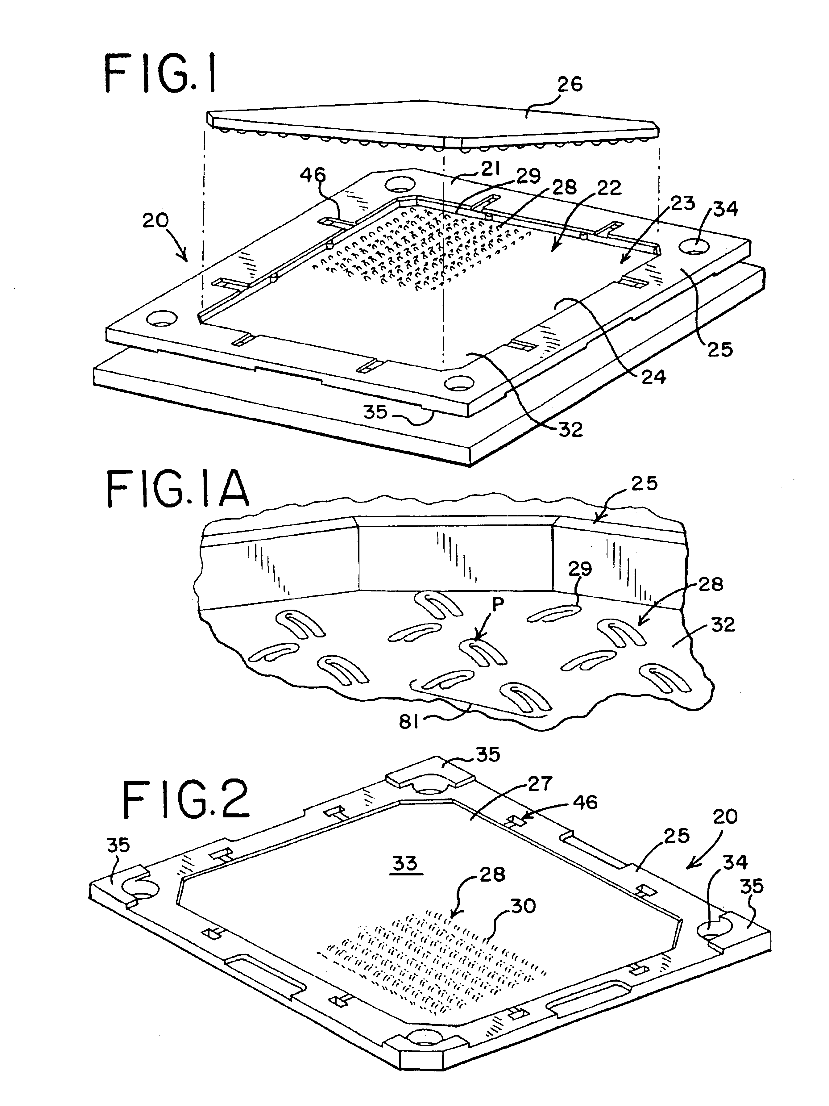
[0074]FIG. 1 illustrates an improved land grid array (“LGA”) connector 20 constructed in accordance with the principles of the present invention. The connector 20 includes a frame member 21 that holds, or encloses, a flexible body portion 22 at the connector 20 disposed within an opening 23 of the frame member 21. The body portion 22 of the connector 20 is held within the frame member opening 23 by a plurality of sidewalls 25 of the frame member 21 that surround the opening 23 in a manner such that a top recess 24 may be defined in the top surface of the connector 20, as well as a bottom recess 27, if the particular application of the connector warrants it.

[0075]It can be seen that the connector 20 is generally rectangular or square in shape, although it will be understood that other configurations may be used. The top recess 24 is adapted to receive therein a circuit component, such as a chip, IC package, ASIC, microprocessor, circuit board 26 or the like, while another similar cir...


PUM


Abstract

A land grid array connector is formed by attaching a reinforcing member to a frame and coating the reinforcing member with an elastomeric compound to form a reinforced, flexible body portion of the connector. Conductive wires are inserted in pairs in an array in the fabric extent. Free ends of the wires extend past the elastomeric compound to provide contacts of the connector. The pairs of wires provide redundancy for the contacts to ensure a reliable connection.

Description

REFERENCE TO RELATED APPLICATIONS[0001]This application is a divisional application of prior application Ser. No. 09 / 815,113 filed Mar. 22, 2001 now U.S. Pat. No. 6,722,896.BACKGROUND OF THE INVENTION[0002]The present invention relates generally to pressure contact connectors, and more particularly to a land grid array (“LGA”) connector that uses a plurality of wires as contacts that are held in a flexible body portion of the connector.[0003]The electronics industry has seen a large growth in the past few years of reduced size electronic devices and appliances, such as laptop computers and the like. The industry is always seeking to reduce the size of these components and to increase their functionality and capability. Both aims are accomplished by increasing the density of circuits on components of the device. Although the number of circuits established on a chip or circuit board may be increased, care must be taken to ensure that a reliable interconnection is established between t...

Claims


Application Information

Patent Timeline
Patent Type & Authority Patents(United States)
IPC IPC(8): H01R43/00H05K7/10H01R13/24H01R13/22H01R33/76H01R12/71
CPCH01R43/007H05K7/1069H01R13/2414H01R12/716H01R12/50
Inventor MCGRATH, JAMES L.LOPATA, JOHN E.DUTTA, ARINDUMMENZIN, MARVINFISHER, JR., DANIEL
Owner MOLEX INC
Why Eureka
Try Eureka