Polishing apparatus

a technology of polishing apparatus and concave, which is applied in the direction of cleaning using liquids, lapping machines, abrasive surface conditioning devices, etc., can solve the problems of clogging concave concave, difficult to remove the attached polishing liquid by cleaning, and affecting the polishing efficiency, etc., to achieve high polishing performance, effective removal of foreign matter clogging concave, and high polishing quality

Inactive Publication Date: 2005-10-11
EBARA CORP
View PDF14 Cites 30 Cited by
  • Summary
  • Abstract
  • Description
  • Claims
  • Application Information

AI Technical Summary

Benefits of technology

[0010]The present invention has been made in view of the above drawbacks. It is, therefore, an object of the present invention to provide a polishing apparatus and a dressing method which can effectively remove foreign matter clogging concavities formed in a polishing surface to regenerate the polishing surface so as to have a high polishing performance and to achieve high-quality polishing.
[0012]The first dresser comprises a dresser, for example, a diamond dresser, capable of shaving a surface of a polishing surface. The present invention is suitable for use of a polishing pad or a fixed abrasive having concavities such as grooves or fine holes formed in a surface (polishing surface) thereon, as shown in FIG. 2. As described above, when a polishing process and a dressing process are repeatedly performed, concavities formed in the polishing surface, such as grooves or fine holes, for enhancing a capability of holding a polishing liquid on a polishing surface, are clogged with foreign matter such as polishing wastes and polishing liquid used in the polishing process, or dressing wastes produced by the dressing process. According to the present invention, foreign matter can be scraped from the concavities in the polishing surface with the second dresser (brush dresser). Therefore, the polishing surface can be regenerated so as to have a high polishing performance, and high-quality polishing can be achieved for subsequent workpieces. Further, it is possible to recover a polishing rate at a central portion of the surface of the workpiece, which has been lowered by repetition of a polishing process and a dressing process, to a level equal to that of a new polishing surface.
[0013]In this case, the second dresser (brush dresser) may not perform dressing when a polishing liquid is supplied to the polishing surface for the following reasons. A polishing liquid supplied onto the polishing surface for polishing a workpiece is removed from the polishing surface by use of the second dresser to thereby lower efficiency of polishing. When the second dresser is used while supplying a polishing liquid, a large amount of polishing liquid is attached to a brush of the second dresser, and it becomes difficult to remove the attached polishing liquid by cleaning.
[0014]According to a preferred aspect of the present invention, a liquid composed of a mixture of a liquid or inert gas with pure water or a chemical liquid is ejected onto the polishing surface to clean the polishing surface. When such a mixed liquid is ejected onto the polishing surface, polishing liquid or polishing wastes can effectively be removed from the polishing surface. In this case, gas in the liquid or the mixed liquid serves not only to remove a polishing liquid and polishing wastes from the polishing surface, but also to scrape a polishing liquid and polishing wastes clogging concavities formed in the polishing surface. Therefore, the atomization during dressing by the second dresser is effective in addition to the aforementioned effect due to the second dresser (brush dresser).
[0020]According to another preferred aspect of the present invention, the brush dresser has a brush having a shape corresponding to a shape of the concavities formed in the polishing surface. With a brush having a shape corresponding to a shape of the concavities formed in the polishing surface, foreign matter can more effectively be scraped from the concavities in the polishing surface. For example, bristles having a diameter smaller than widths of grooves (concavities) may be implanted in a brush dresser. Alternatively, elasticity of bristles in a brush dresser may be set so as to correspond to depth of grooves (concavities). The diameter of bristles and the elasticity of bristles can be changed by selecting materials for bristles.

Problems solved by technology

As described above, when a polishing process and a dressing process are repeatedly performed, concavities formed in the polishing surface, such as grooves or fine holes, for enhancing a capability of holding a polishing liquid on a polishing surface, are clogged with foreign matter such as polishing wastes and polishing liquid used in the polishing process, or dressing wastes produced by the dressing process.
A polishing liquid supplied onto the polishing surface for polishing a workpiece is removed from the polishing surface by use of the second dresser to thereby lower efficiency of polishing.
When the second dresser is used while supplying a polishing liquid, a large amount of polishing liquid is attached to a brush of the second dresser, and it becomes difficult to remove the attached polishing liquid by cleaning.

Method used


Image

  • Polishing apparatus
  • Polishing apparatus
  • Polishing apparatus

Examples


Embodiment Construction

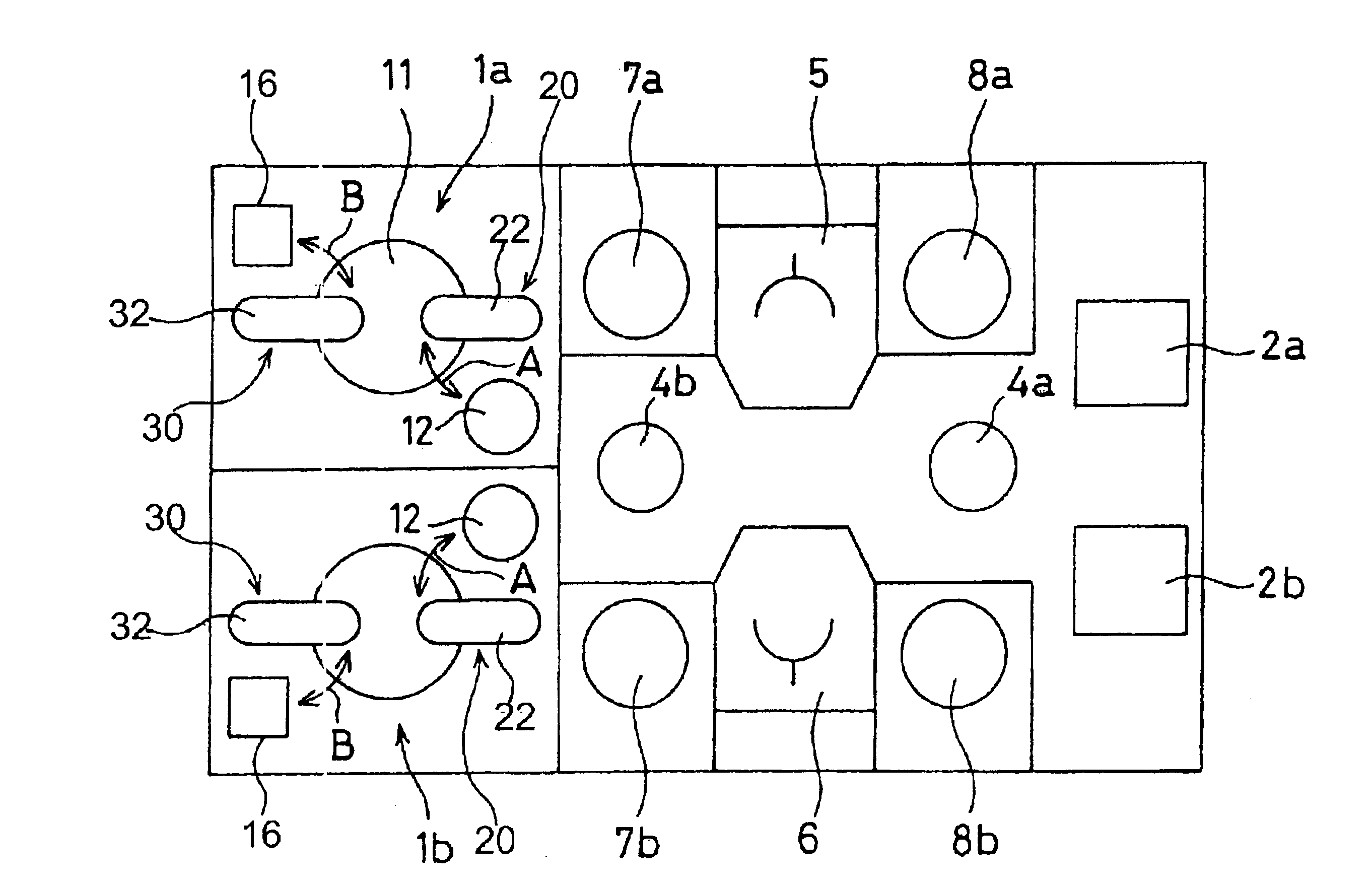
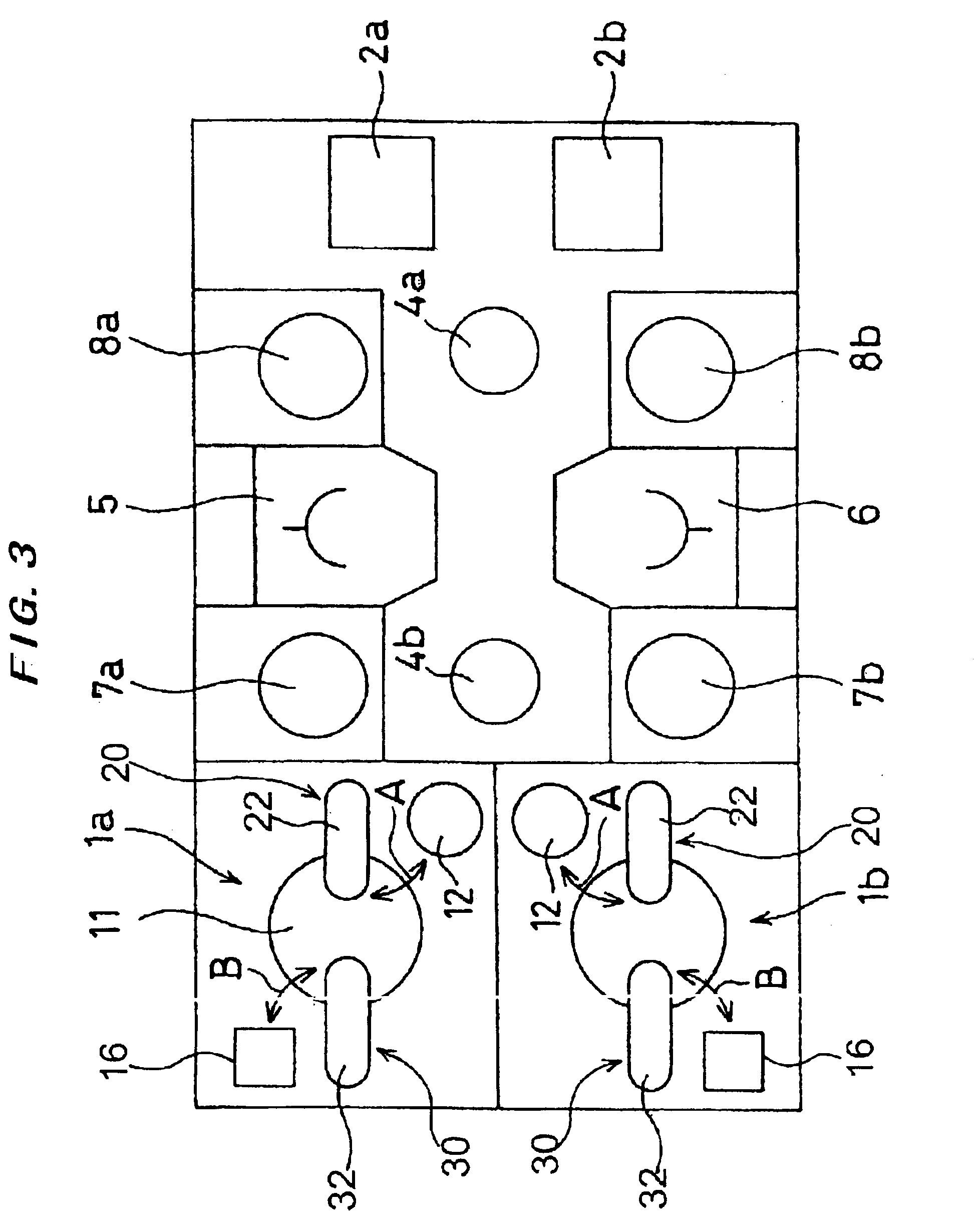
[0041]A polishing apparatus according to a first embodiment of the present invention will be described below with reference to FIGS. 3 through 12. FIG. 3 is a schematic plan view showing a polishing apparatus according to the first embodiment of the present invention.

[0042]As shown in FIG. 3, the polishing apparatus has a housing, for example, having a rectangular shape, a pair of polishing sections 1a, 1b, for example, disposed on one side of the housing so as to face each other, and a pair of load / unload units, for example, disposed on the other side of the housing for receiving cassettes 2a, 2b which accommodate a plurality of semiconductor wafers. Two transfer robots 4a, 4b for transferring semiconductor wafers are disposed, for example, on a line connecting the polishing sections 1a, 1b to the load / unload units, to form a transfer line. Two inverters 5, 6 are disposed on both sides of the transfer line, and two sets of cleaning units 7a, 7b and 8a, 8b are disposed on both sides...


PUM

PropertyMeasurementUnit
shapeaaaaaaaaaa
distancesaaaaaaaaaa
pressureaaaaaaaaaa

Abstract

A polishing surface is conditioned by pressing a diamond dresser against the polishing surface to thinly shave a surface of the polishing surface. Foreign matter clogging concavities formed in the polishing surface is scraped by pressing a brush dresser against the polishing surface in a state such that a polishing liquid is not supplied to the polishing table. A liquid composed of a mixture of a liquid or inert gas with pure water or a chemical liquid is ejected onto the polishing surface to clean the polishing surface.

Description

BACKGROUND OF THE INVENTION[0001]1. Field of the Invention[0002]The present invention relates to a polishing apparatus for polishing a workpiece, and more particularly to a polishing apparatus for polishing a workpiece having a thin film formed thereon, such as a semiconductor wafer, to a flat mirror finish. The present invention also relates to a method of dressing a polishing surface, and more particularly to a method of dressing a polishing surface serving to polish a workpiece such as a semiconductor wafer by sliding contact.[0003]2. Description of the Related Art[0004]As semiconductor devices have become more highly integrated in recent years, circuit interconnections have become finer and distances between those circuit interconnections have become smaller. In a case of photolithography, which can form interconnections that are at most 0.5 μm wide, it is required that surfaces on which pattern images are to be focused by a stepper should be as flat as possible because a depth ...

Claims


Application Information

Patent Timeline
Patent Type & Authority Patents(United States)
IPC IPC(8): B08B3/10B08B3/12B24B53/00B24B53/02B24B53/007B24B53/013B24B37/04B24B53/017H01L21/304
CPCB08B1/007B08B3/102B08B3/12B24B53/013B24B53/017B24B53/02
Inventor SAKURAI, KUNIHIKOYOSHIDA, HIROSHITOGAWA, TETSUJI
Owner EBARA CORP
Why Eureka
Try Eureka