
Solid electrolytic capacitor and method for producing the same

Active Publication Date: 2005-10-11
MURATA MFG CO LTD
View PDF5 Cites 28 Cited by
  • Summary
  • Abstract
  • Description
  • Claims
  • Application Information

AI Technical Summary

Benefits of technology

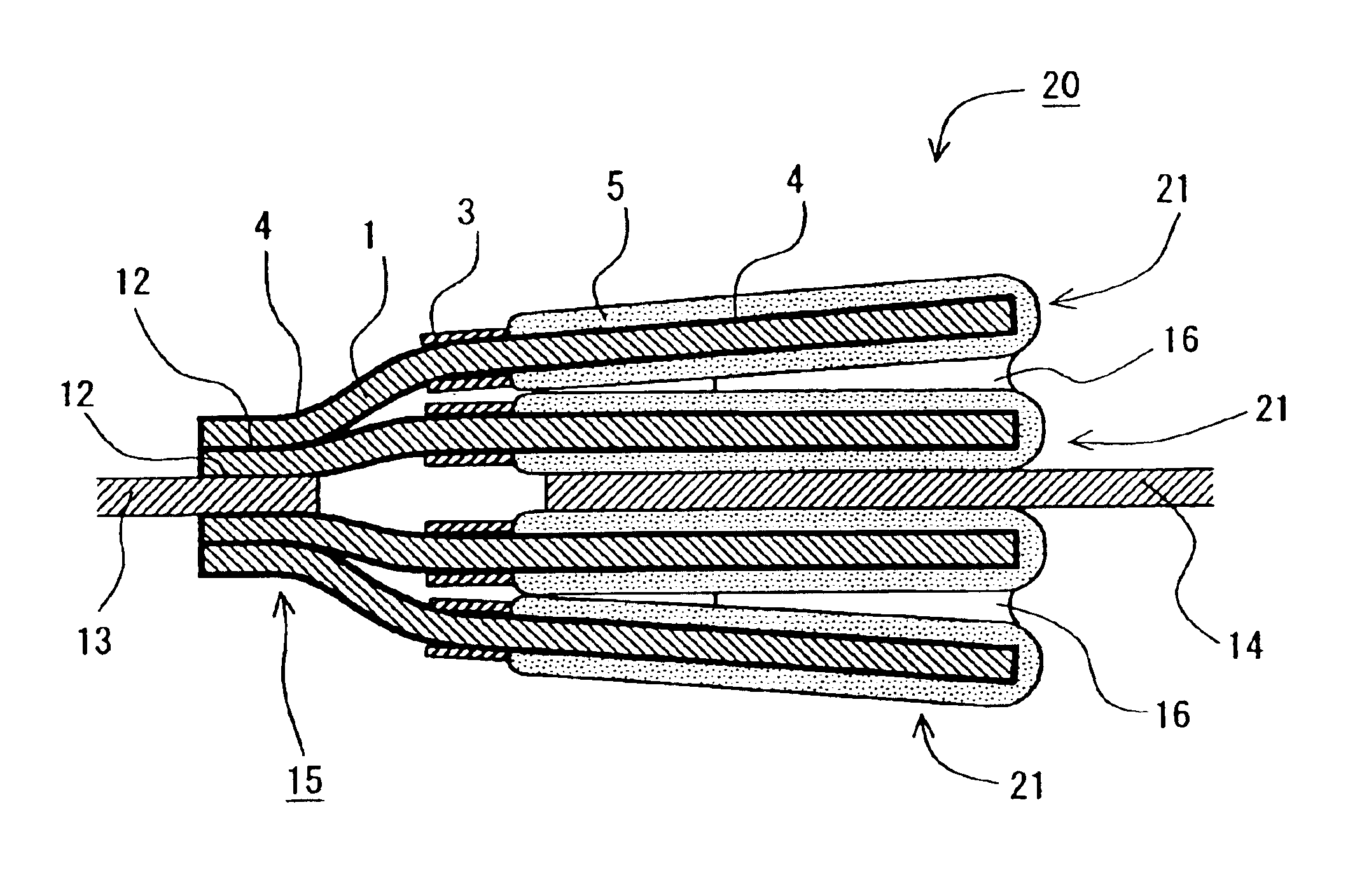
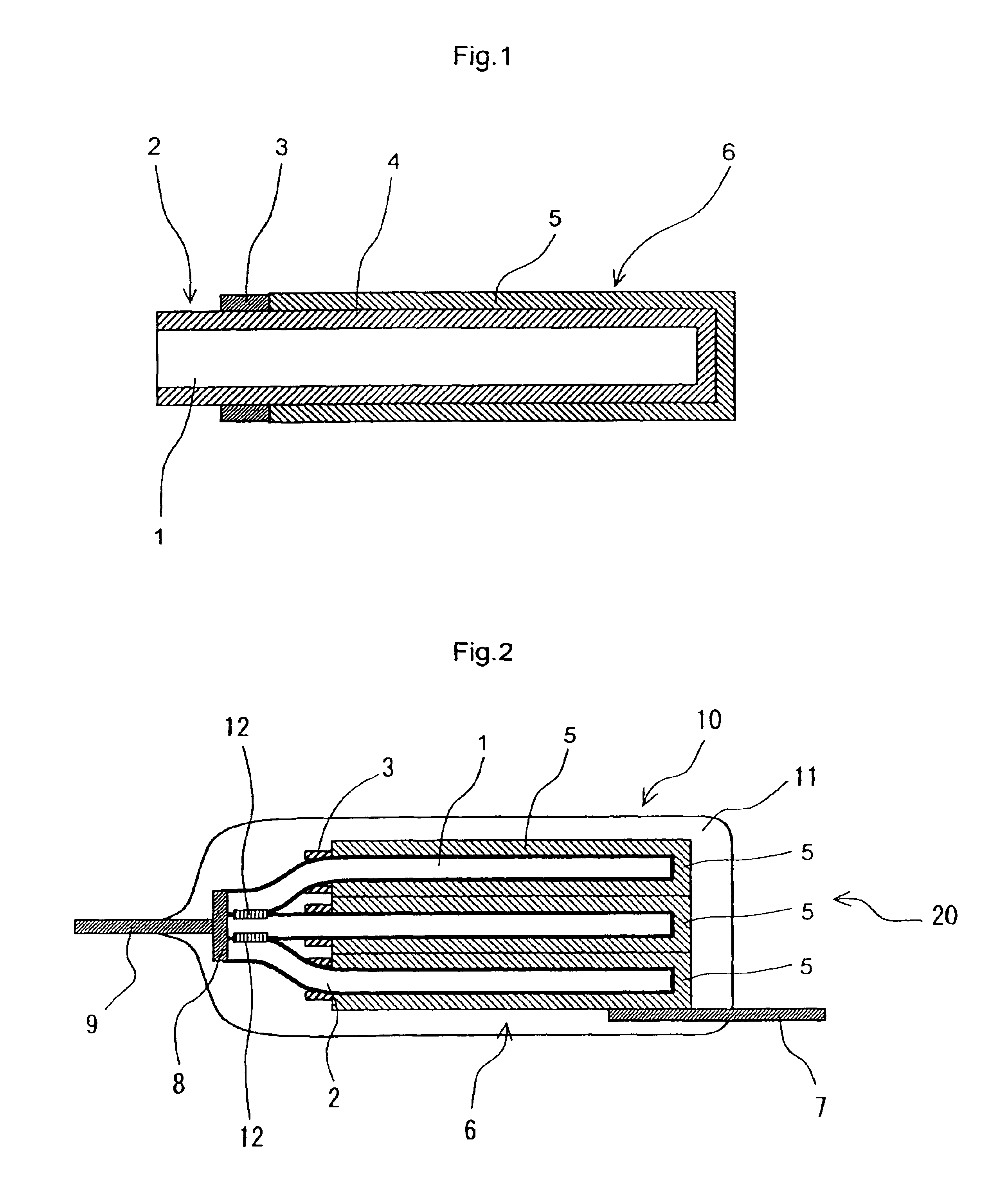
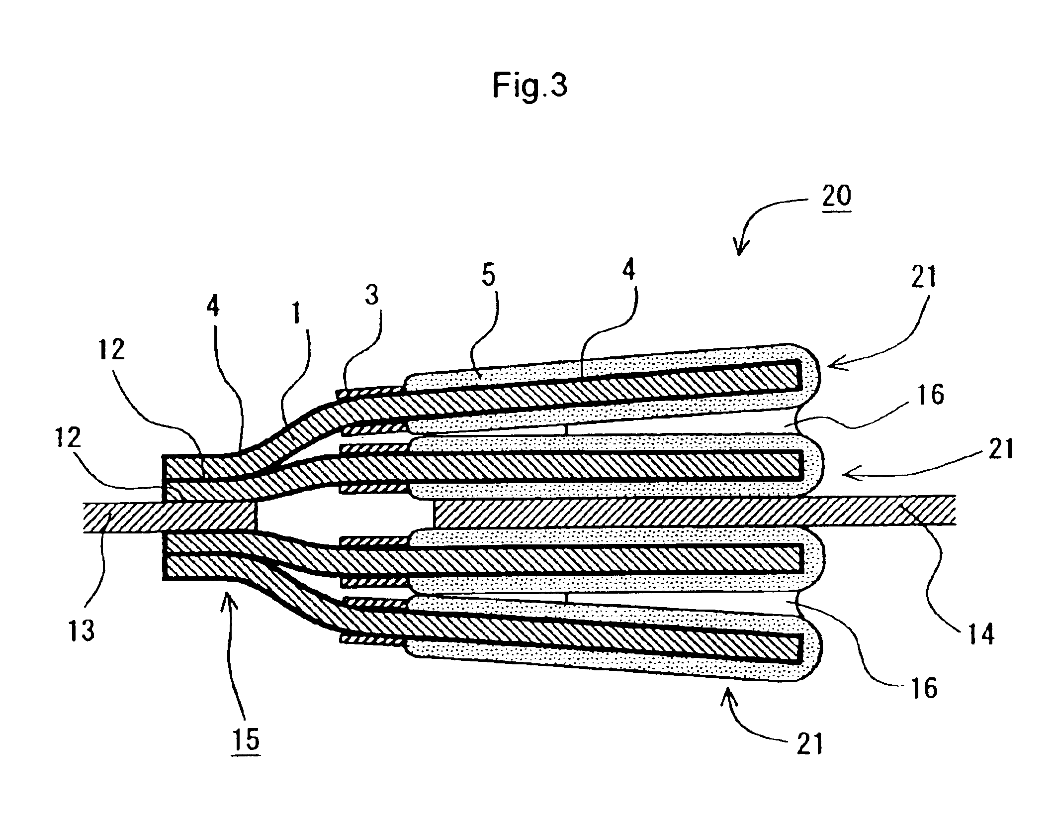
[0011]The object of the present invention is to provide a method for producing a solid electrolytic capacitor, where when an electrically conducting polymer to work out to be a solid electrolyte is formed on an oxide dielectric film and the anode part of a valve-acting metal substrate on the same surface and an anode leadwire are connected by resistance welding, the welding failure is reduced and the production yield is improved. The present invention also provides a solid electrolytic capacitor produced by this production method.
[0012]As a result of extensive investigations to solve the above-described problems, the present inventors have found that when electrically insulating inorganic particles of a metal oxide are adhered by coating, spraying or the like to at least a part of the surface in the anode part of an electrochemically formed foil and then, resistance welding is performed using an electrical energy, surprisingly, the bonding strength between the anode part of the electrochemically formed foil and the anode lead is improved, whereby the production yield of capacitor is elevated and the dispersion in the properties among individual capacitors is reduced.

Problems solved by technology

However, the bonding using an electrically conducting adhesive takes time in coating the viscous adhesive.
Particularly, in the case of stacking and bonding a plurality of capacitor elements, the application is cumbersome.
The mechanical bonding using a caulking is not suitable for the case where the bonding portion is small, and the bonding is unstable.
The bonding by laser welding has a problem in that the equipment therefor costs highly.
Moreover, because of good thermal conductivity, the bonding portion cannot be satisfactorily fused.
Accordingly, it is difficult to find out good conditions for welding and a problem of connection failure with the anode lead is present.

Method used


Image

  • Solid electrolytic capacitor and method for producing the same
  • Solid electrolytic capacitor and method for producing the same
  • Solid electrolytic capacitor and method for producing the same

Examples


example 1

[0079]A formed aluminum foil (100LJ19B4Vf, trade name, produced by Japan Capacitor Industrial Co., Ltd. (JCC)) (rated film withstand voltage: 4 Vf) was cut and a masking material (heat resistant resin) (3) was circumferentially formed 1 mm in width on both surfaces and at both ends of the foil to divide the foil into two parts from the distal end. Thus, the foil was divided into the cathode part (3 mm×4 mm)(6) and the anode part(2), and the cathode part assigned to the divided portion in the distal end side was subjected to electrochemical forming in an aqueous 5% by mass oxalic acid solution at 25° C. for 120 seconds and then washed with water.

[0080]Subsequently, the foil was heat-treated at 350° C. for 3 minutes and then electrochemically formed using an aqueous 10% by mass ammonium adipate solution as the electrolytic solution under the conditions such that the temperature was 55° C., the voltage was 4 V, the current density was 5 mA / cm2 and the current passing time was 10 minute...

example 2

[0092]50 Capacitor elements were manufactured in the same manner as in Example 1 except for using a 0.5% by mass alumina (the property of alumina particle was the same as in Example 1) dispersion solution in place of the 0.1% by mass alumina dispersion solution in Example 1. These specimens were evaluated in the same manner as in Example 1. The results obtained are shown in Tables 1 and 2.

example 3

[0093]50 Capacitor elements were manufactured in the same manner as in Example 1 except for using a 1% by mass zirconia (containing particles having a primary particle size of 2 μm or less in a proportion of 70% or more) dispersion solution in place of the 0.1% by mass alumina dispersion solution in Example 1. These specimens were evaluated in the same manner as in Example 1. The results obtained are shown in Tables 1 and 2.


PUM

PropertyMeasurementUnit
Thicknessaaaaaaaaaa
Thicknessaaaaaaaaaa
Electric potential / voltageaaaaaaaaaa

Abstract

A method for producing a solid electrolytic capacitor, involving a step of loading a metal oxide on at least a part of the surface in the anode part of a capacitor element having a valve-acting metal substrate having there on a solid electrolyte, the valve-acting metal substrate having a dielectric film obtained by the electrochemical forming, and a solid electrolytic capacitor obtained by stacking two or more single plate capacitor elements having a metal oxide on at least a part of the surface in the anode part of a capacitor element comprising a valve-acting metal substrate having thereon a solid electrolyte, the valve-acting metal substrate having a dielectric film obtained by the electrochemical forming.

Description

CROSS-REFERENCE TO RELATED APPLICATIONS[0001]This is an application filed pursuant to Section 111 (a) with a claim to priority to Provisional Application Serial No. 60 / 315,033 filed on Aug. 28, 2001 pursuant to 35 U.S.C. Section 119(e) (1) in accordance with 35 U.S.C. 111(b).TECHNICAL FIELD[0002]The present invention relates to a solid electrolytic capacitor and a method for producing the capacitor. More specifically, the present invention relates to a solid electrolytic capacitor comprising a valve-acting metal substrate having thereon a dielectric film with the anode part thereof being subjected to welding by resistance heating, wherein the welding failure of the anode part is improved, and also relates to a method for producing the capacitor.BACKGROUND ART[0003]A solid electrolytic capacitor has a fundamental structure constructed by forming a high-density and uniform oxide dielectric film on the surface of a valve-acting metal previously etched to roughen the surface, such as al...

Claims


Application Information

Patent Timeline
IPC IPC(8): H01G9/00H01G9/012H01G9/15
CPCH01G9/012H01G9/028H01G9/15Y10T29/417
Inventor KONUMA, HIROSHIKOMAZAWA, EIJIYAMAZAKI, KATSUHIKO
Owner MURATA MFG CO LTD
Features
  • Generate Ideas
  • Intellectual Property
  • Life Sciences
  • Materials
  • Tech Scout
  • Unparalleled Data Quality
  • Higher Quality Content
  • 60% Fewer Hallucinations
Learn More