Method and apparatus for manufacturing a catalytic converter

a manufacturing method and catalytic converter technology, applied in the direction of machines/engines, physical/chemical process catalysts, separation processes, etc., can solve the problems of inability to monitor the manufacturing process, inability to measure deformation alone, and different fracture characteristics of geometries

Inactive Publication Date: 2005-10-18
COMERICA BANK +1
View PDF18 Cites 43 Cited by
  • Summary
  • Abstract
  • Description
  • Claims
  • Application Information

AI Technical Summary

Benefits of technology

[0013]The ends of the tube can also be necked down to a smaller profile, somewhat funnel-like. The ends of the tube may be necked down by spinning, such that the ends have diameters smaller than the profile of the remainder of the outer tube. Also in one embodiment, prior to the spinning step, funnel-shaped heat shields are inserted into opposite ends of the outer tube, and adjacent to the monolith substrate, and the outer tube is spun in order that the ends are spun down to substantially conform to the profile of the heat shield, and retain the heat shield in place.

Problems solved by technology

One of the difficulties in working with such substrates is that several different geometries exist, and different geometries have different fracture characteristics.
Thus the deformation alone cannot be measured.
Furthermore, it has not heretofore been possible to monitor the manufacturing process in light of such fracture characteristics to enable proper manufacturing of the catalytic converters with the proper load between the mat material and the monolith, without causing fracture of some of the monoliths.

Method used


Image

  • Method and apparatus for manufacturing a catalytic converter
  • Method and apparatus for manufacturing a catalytic converter
  • Method and apparatus for manufacturing a catalytic converter

Examples


Embodiment Construction

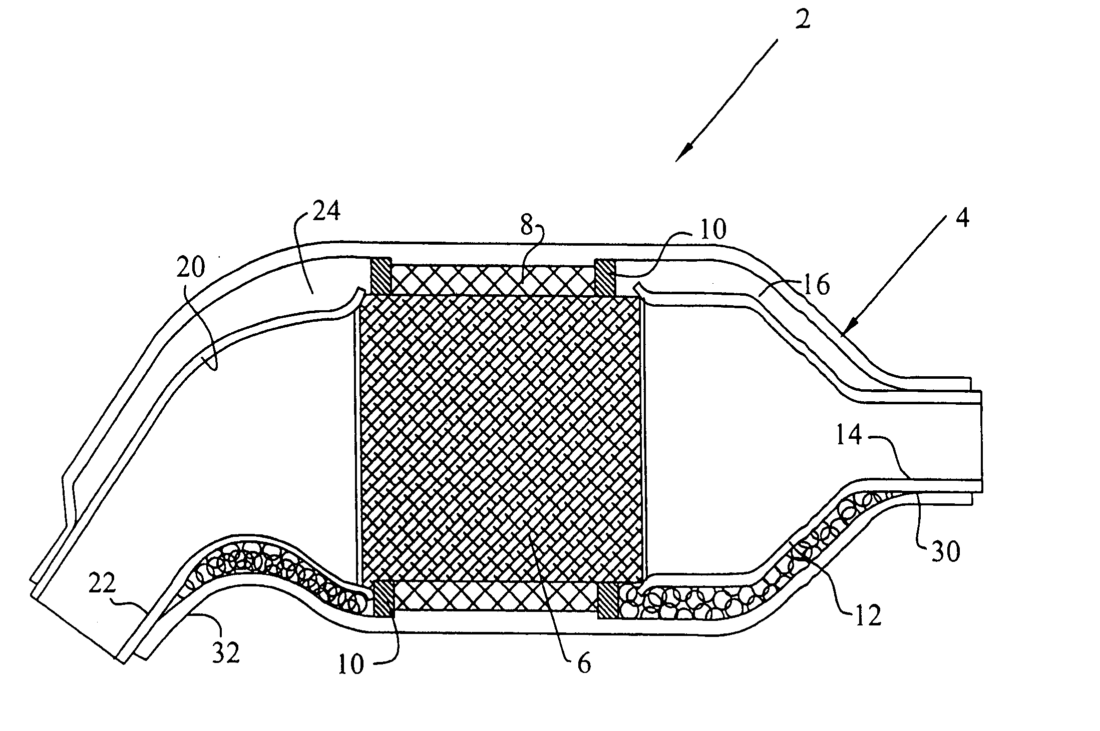
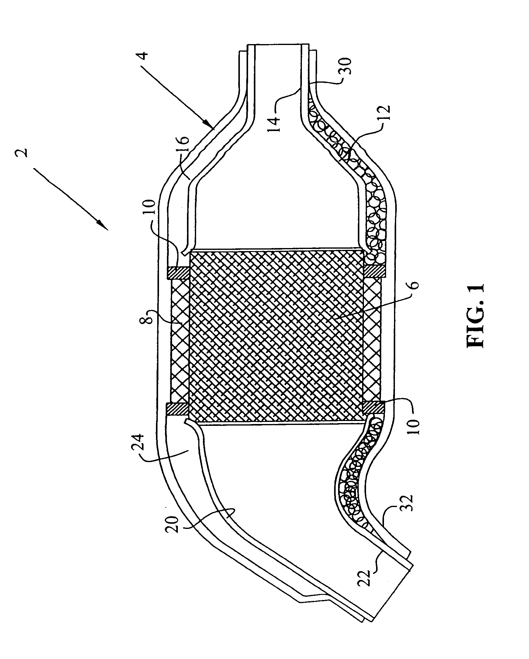
[0031]With reference first to FIG. 1, an example of a catalytic converter manufactured according to the process of the present invention is shown generally at 2, and includes an outer tube member 4, a monolith substrate 6, a mat material 8 with end seal members 10. The catalytic converter 2 can also optionally include a first heat shield member 12 having a necked-down section 14, thereby forming an internal air gap at 16. The catalytic converter 2 can also include a second heat shield member 20 having a necked-down section 22 forming an air gap at 24. It should be appreciated to those skilled in the art that the mat material 8 can either be a stainless steel mesh-type material, or can alternatively be a nonflammable, fibrous-type material. In either case, the mat material 8 is compressible but, when compressed in the combination of the monolith 6, mat material 8, and outer tube 4, causes a force transfer from the mat material to the monolith substrate 6, and an equal reaction force ...


PUM

PropertyMeasurementUnit
pressureaaaaaaaaaa
pressureaaaaaaaaaa
diametersaaaaaaaaaa

Abstract

A method of manufacturing a catalytic converter is described where the catalytic converter is comprised of an outer tube member having a monolith substrate internally compressed therein with a wrapped mat material surrounding the monolith substrate and intermediate the outer tube. One or more monolith members can be applied within the outer tube and heat shields may also be applied internal to the outer tube and adjacent to the monolith substrate. The assembly of the catalytic converter includes measuring the sequence of compression of the mat material to the monolith substrate in order to understand the possible force characteristics which can be applied during the assembly thereof. The mat material is therefore compressed within the outer tube by way of compression jaws, by compression rollers, and/or by spinning. The compression of the mat material can be in single or multiple steps.

Description

[0001]This application claims the benefit of U.S. Provisional Patent Application Ser. No. 60 / 291,894 filed May 18, 2001, the complete disclosure of which is hereby expressly incorporated by reference.BACKGROUND OF THE INVENTION[0002]The invention generally relates to the manufacturing of catalytic converters for automotive use.[0003]It is common in automotive applications to require a catalytic converter in the exhaust system of automobiles, typically placed between the engine exhaust manifold and the muffler system of the automobile. As disclosed in U.S. Pat. No. 5,482,686, the catalytic converter normally includes a monolith substrate, a mat material surrounding the monolith substrate, the monolith and mat material then being encapsulated in a metal enclosure which can be a cylindrical tube, a bipartite metal enclosure, or other round or non-round-type metal housing. It is also common to seal opposite ends of the mat material against the internal surface of the metal housing.[0004...

Claims


Application Information

Patent Timeline
Patent Type & Authority Patents(United States)
IPC IPC(8): F01N7/14F01N3/28F01N7/18B01D53/86B01J33/00B21D53/84F01N13/14F01N13/18
CPCB21D53/02F01N3/2842F01N13/14F01N13/18F01N3/2853F01N2330/06Y10T29/49913F01N2450/02Y10T29/53396Y10T29/53422Y10T29/49345Y02E50/14F01N2350/04Y02E50/10
Inventor MAYFIELD, DAVID
Owner COMERICA BANK
Why Eureka
Try Eureka