

Differential oscillator circuit including an electro-mechanical resonator
- Summary
- Abstract
- Description
- Claims
- Application Information
AI Technical Summary
Benefits of technology
Problems solved by technology
Method used
Image

Examples
first embodiment
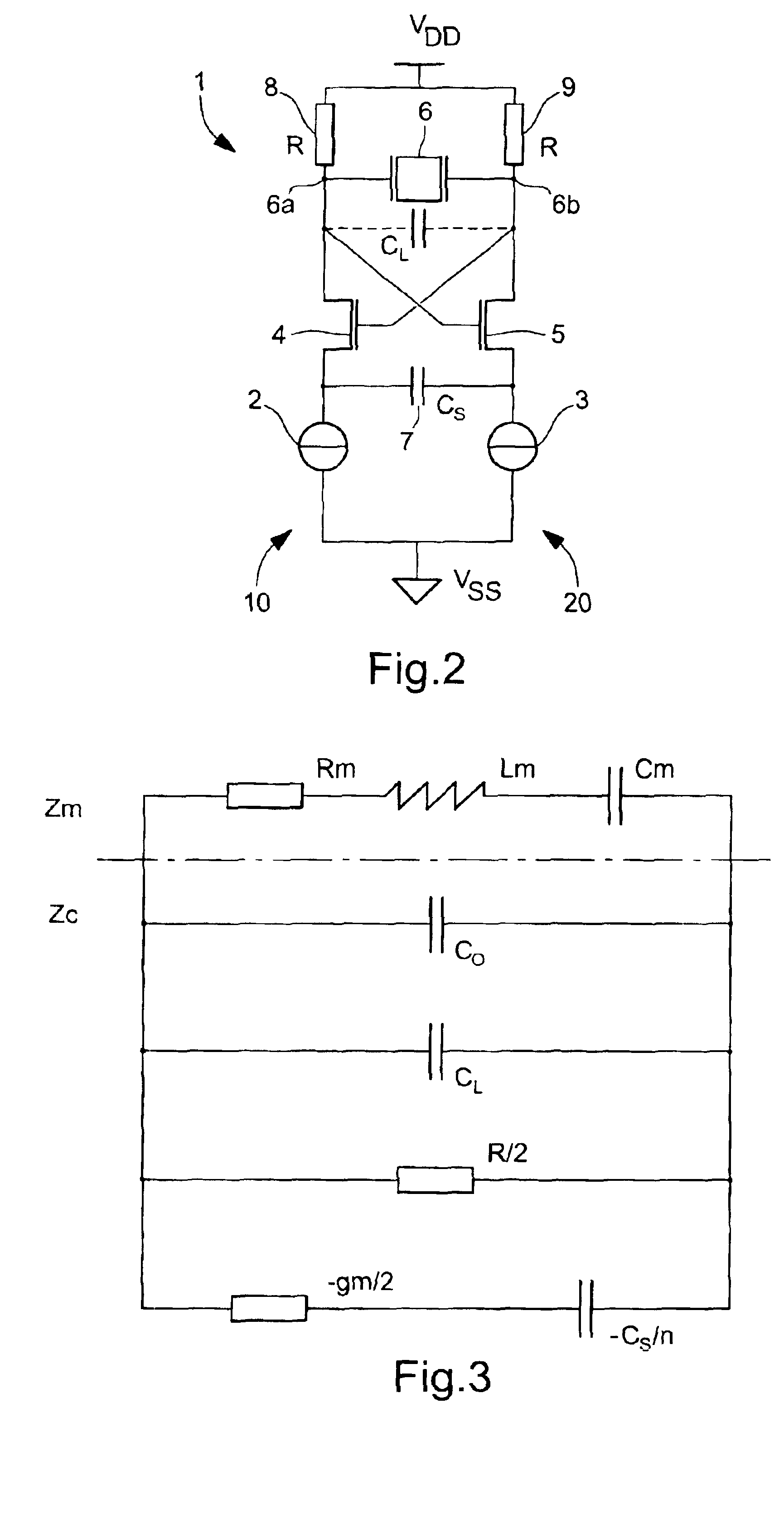
[0037]FIG. 2 shows a diagram of a differential oscillator circuit, globally indicated by the reference numeral 1, constituting the present invention.
[0038]This differential oscillator circuit 1 includes, generally, first and second branches, respectively designated by the reference numerals 10 and 20, each connected between a high supply potential VDD and a low supply potential VSS. These branches are identical and each include, starting from high supply potential VDD, the series arrangement of a resistive element 8, respectively 9, an n-MOS transistor 4, respectively 5, and a current source 2, respectively 3. More specifically, one of resistive elements 8, 9 is connected between supply potential VDD and the drain of transistor 4, and the other is connected between supply potential VDD and the drain of transistor 5. Likewise, one of current sources 2, 3 is connected between supply potential VSS and the source of transistor 4, and the other is connected between supply potential VSS a...
second embodiment
[0044]Generally, and as will be seen in detail hereinafter with reference to the present invention, current sources 2, 3 can allow regulation of the oscillation amplitude if placed in a suitable oscillation amplitude regulating loop.
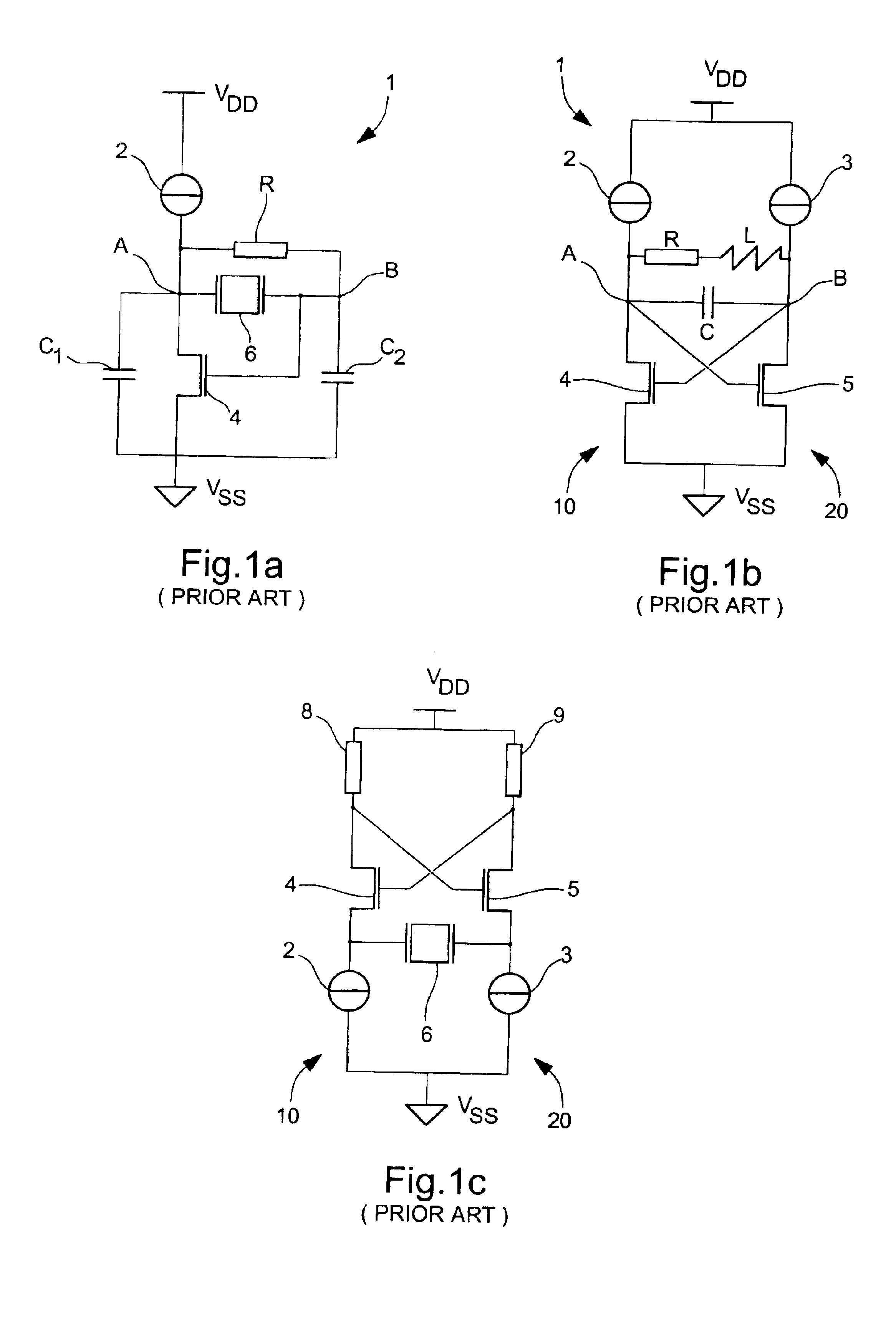
[0045]As already mentioned in the preamble, the structure illustrated in FIG. 2 performs better in terms of power consumption than the Pierce oscillator circuit illustrated in FIG. 1a. Indeed, the use of load capacitive elements on either side of the electro-mechanical resonator can be omitted without altering the behaviour or frequency stability of the oscillator.
[0046]A small-signal analysis of the impedance (or admittance) seen outside the motional branch of the crystal oscillator (Rm Lm Cm) allows a precise determination of the conditions leading or not to relaxation. With CO the shunt capacitance of the crystal resonator, CL, CS the equivalent differential capacitances seen respectively between the two drains and the two sources of the cross-coupled...
PUM
 Abstract
Description
Claims
Application Information