High temperature stable thermal interface material

a thermal interface and high temperature stable technology, applied in the direction of electrical apparatus construction details, transportation and packaging, synthetic resin layered products, etc., can solve the problem of not being specified for more demanding applications, and achieve the effect of low thermal impedan

Inactive Publication Date: 2005-10-18
PARKER INTANGIBLES LLC
View PDF60 Cites 42 Cited by
  • Summary
  • Abstract
  • Description
  • Claims
  • Application Information

AI Technical Summary

Benefits of technology

[0025]FIG. 4 is a cross-sectional view of a representative thermal management assembly wherein the heat sink and interface of FIG. 3 are disposed in heat transfer adjacency with a heat genera

Problems solved by technology

Such materials, although being highly conformable and affording excellent thermal performance, genera

Method used


Image

  • High temperature stable thermal interface material
  • High temperature stable thermal interface material
  • High temperature stable thermal interface material

Examples


Embodiment Construction

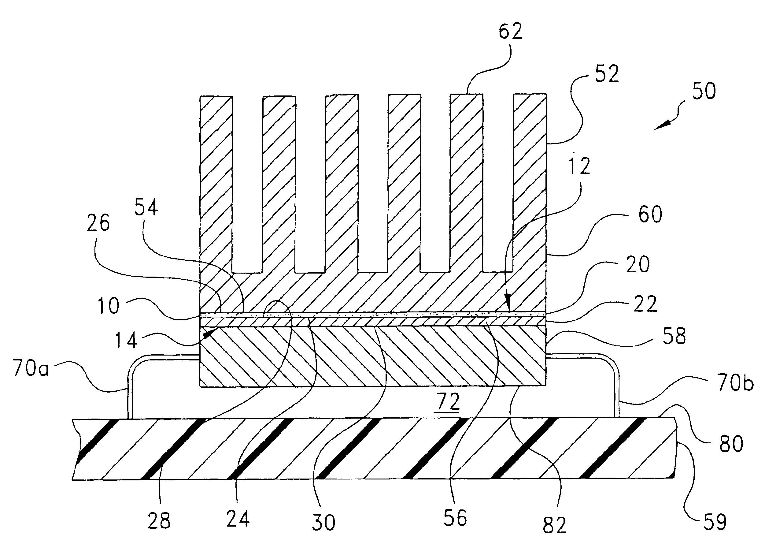
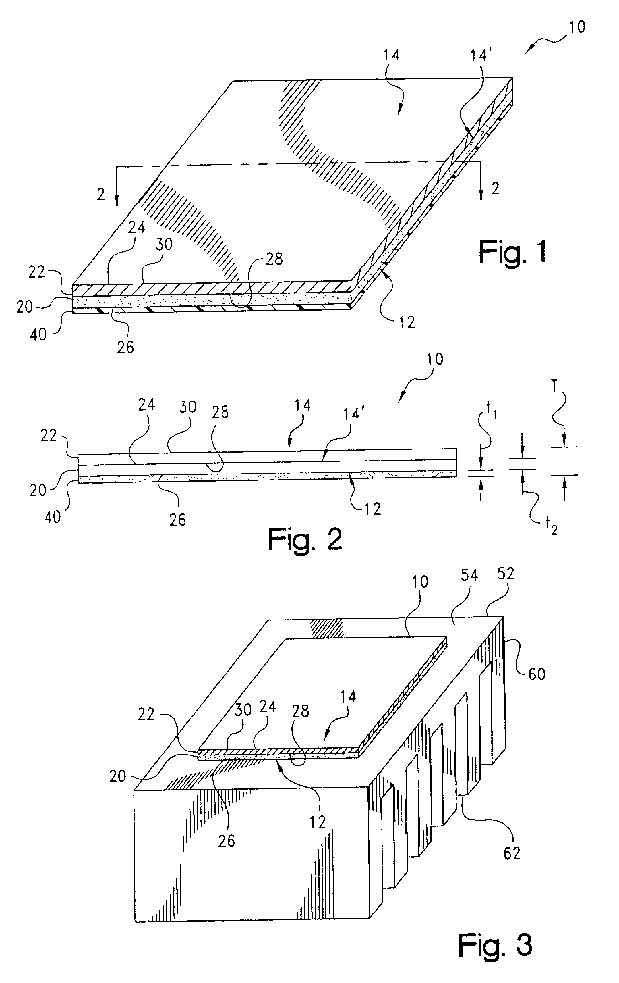
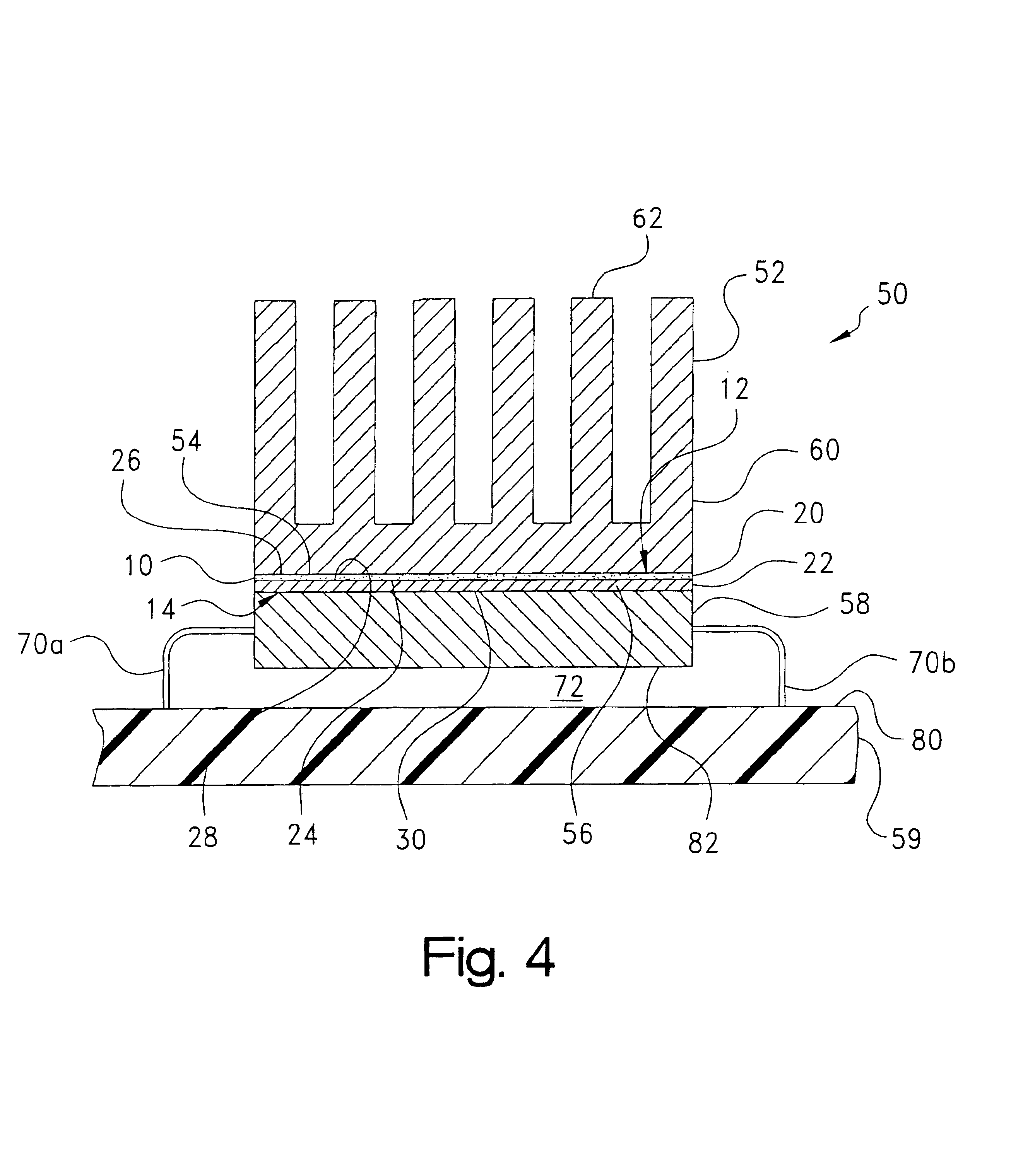
[0027]Certain terminology may be employed in the following description for convenience rather than for any limiting purpose. For example, the terms “forward” and “rearward,”“front” and “rear,”“right” and “left,”“upper” and “lower,”“top” and “bottom,” and “right” and “left” designate directions in the drawings to which reference is made, with the terms “inward,”“inner,”“interior,” or “inboard” and “outward,”“outer,”“exterior,” or “outboard” referring, respectively, to directions toward and away from the center of the referenced element, the terms “radial” or “vertical” and “axial” or “horizontal” referring, respectively, to directions or planes perpendicular and parallel to the longitudinal central axis of the referenced element. Terminology of similar import other than the words specifically mentioned above likewise is to be considered as being used for purposes of convenience rather than in any limiting sense.

[0028]In the figures, elements having an alphanumeric designation may be ...


PUM

PropertyMeasurementUnit
Temperatureaaaaaaaaaa

Abstract

A thermally-conductive interface interposable intermediate a first heat transfer surface and an opposing second heat transfer surface to provide a thermal pathway therebetween. The interface includes a thermally-conductive compound formed into a layer which is conformable between the first and second heat transfer surface. The compound is an admixture of: (a) a liquid resin constituent; and (b) a particulate filler constituent. The liquid resin constituent may be an ethylene-propylene copolymer (EPM) or a terpolymer (EPDM) of ethylene and propylene and a diene which may be ethylidene norbornene (ENB) or dicyclopentadiene (DCPD).

Description

CROSS-REFERENCE TO RELATED CASES[0001]The present application claims the benefit of the filing date of U.S. Provisional Application Ser. No. 60 / 422,194; filed Oct. 29, 2002, the disclosure of which is expressly incorporated herein by reference.BACKGROUND OF THE INVENTION[0002]The present invention relates broadly to thermal management materials for electronic devices. Such materials commonly are used as interfaces for providing a low thermal impedance between, for example, the mating heat transfer surfaces of a heat-generating, electronic component, such as an integrated circuit (IC) chip, and a thermal dissipation member, such as a heat sink or spreader, for the conductive cooling of the electronic component. More particularly, the present invention relates to a thermally-conductive interface material which is formulated to be stable at higher operating temperatures of about 125° C. or more.[0003]Circuit designs for modern electronic devices such as televisions, radios, computers, ...

Claims


Application Information

Patent Timeline
IPC IPC(8): H01L23/34H01L23/427
CPCH01L23/4275H01L2924/3011Y10T428/2822H01L2924/0002H01L2924/00Y10T428/31909Y10T428/31913Y10T428/31917Y10T428/31938
Inventor BUNYAN, MICHAEL H.
Owner PARKER INTANGIBLES LLC
Why Eureka
Try Eureka