

Contact print methods
- Summary
- Abstract
- Description
- Claims
- Application Information
AI Technical Summary
Benefits of technology
Problems solved by technology
Method used
Image

Examples
Embodiment Construction
[0030]In accordance with the present invention, a micro-device is fabricated by forming a plurality of patterned device layers, wherein one or more of the patterned device layers are formed using liquid embossing with a stamp. Preferably, the printing process is controlled by using a stamp with differentiated protruding surfaces and recessed surfaces, by controlling the printing conditions and / or a combination thereof.
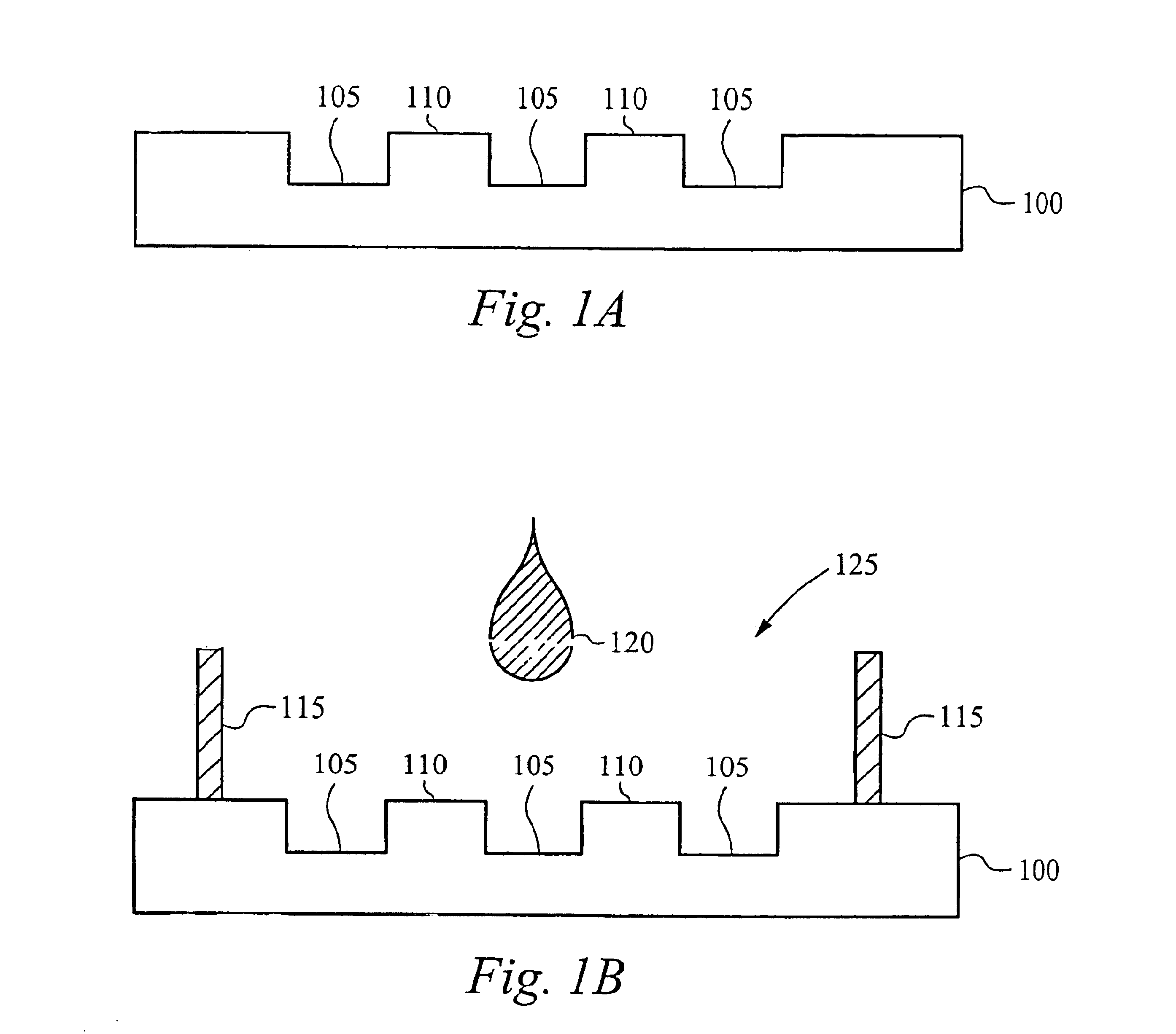
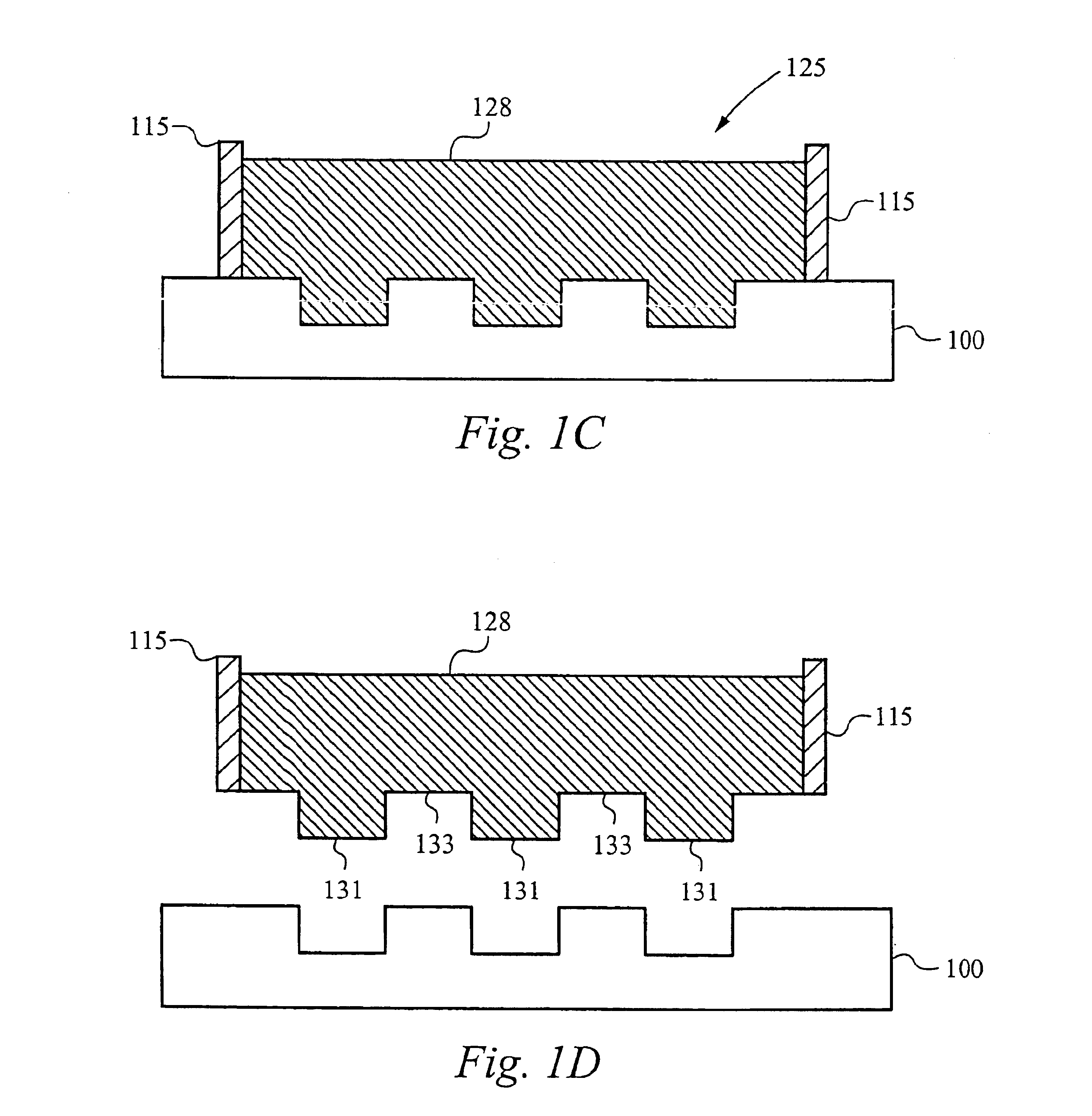
[0031]FIGS. 1A-D illustrate exemplary steps for making an elastomeric stamp structure 128 (FIG. 1D). Referring to FIG. 1A, a master 100 is formed having a series of recessed features 105 and protruding features 110, which provides a negative impression for casting the stamp structure 128. The actual dimensions of the features 105 and 110 depend on the intended application of the stamp structure 128 and are determined by the method used to pattern the master 100. In general, however, feature sizes as small as 150 nanometers are possible using lithography techniques.
[003...
PUM
 Abstract
Description
Claims
Application Information