High pressure and high temperature reaction system
- Summary
- Abstract
- Description
- Claims
- Application Information
AI Technical Summary
Benefits of technology
Problems solved by technology
Method used
Image

Examples
first embodiment
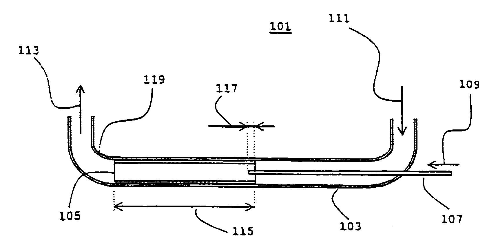
[0034]the present invention, shown in FIG. 2, depicts an apparatus 101 for introducing nitric acid in a supercritical water flow containing ammonia or ammonium with the purpose of converting this to molecular nitrogen.
[0035]In a section of a reaction system tube 103, which preferably is the conduit between the heater 16 and the reaction chamber 18, or part of the reaction chamber itself, of FIG. 1, a separate tube or liner 105 of a corrosion resistant material is mounted, the outer surface of which is in fit with the inner surface of reaction system tube 103. Alternatively, tube 105 constitutes part of the reaction system tube 103 itself (not shown).
[0036]A feeding pipe 107 of relatively small diameter, is mounted through an opening of tube 103 and extends substantially axially with tube 103 and liner 105, and which ends in the interior of tube 103. Preferably, feeding pipe 107 and tube 103 are concentrically arranged for transportation of fluids, the former nitric acid and the latt...
second embodiment
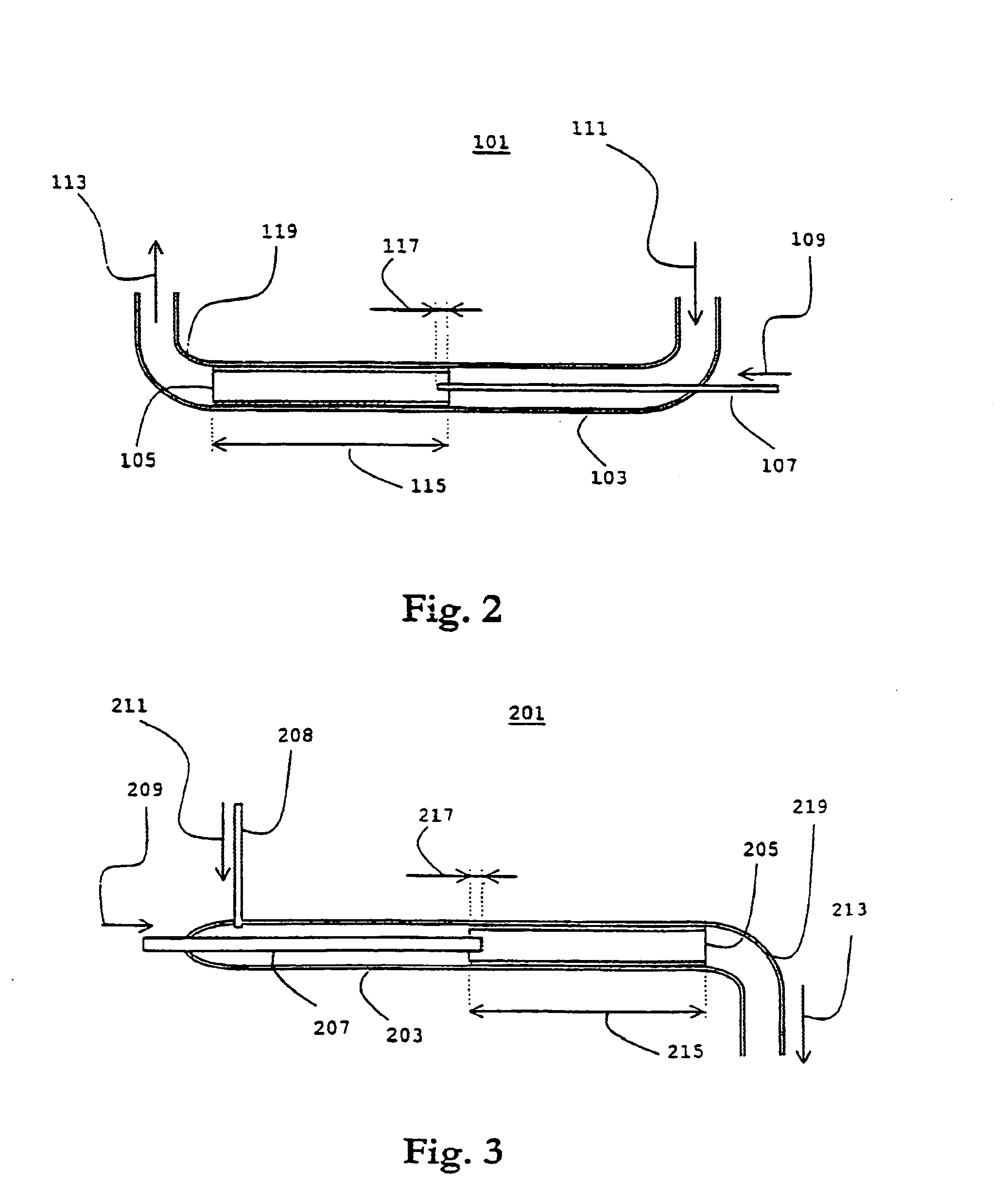
[0045]Referring next to FIG. 3, which illustrates an apparatus 201 according to the present invention, a separate tube or liner 205 of a corrosion resistant material is mounted in a section of a reaction system tube 203, which is preferably at the effluent output or elsewhere in the exit path tubing. The outer surface of liner 205 is arranged to be in fit with the inner surface of the reaction system tube 203.
[0046]A first input tube 207, is mounted through an opening of tube 203 and extends substantially axially, preferably concentrically, with tube 203 and liner 205, and which ends in the interior of tube 203. A second input tube 208 is connected to tube 203 upstream from said end of input tube 207.
[0047]Input tube 207 and input tube 208 are arranged for transporting effluent from reactor 18 containing corrosive compounds such as nitric acid, sulfur acid, or the like, and quench water, respectively, in the directions as indicated by arrows 209–213. The effluent stream is supercrit...
PUM
| Property | Measurement | Unit |
|---|---|---|
| Temperature | aaaaa | aaaaa |
| Temperature | aaaaa | aaaaa |
| Temperature | aaaaa | aaaaa |
Abstract
Description
Claims
Application Information